Dell Latitude 7340 Service Manual
Dell Latitude 7340 Manual
 |
View all Dell Latitude 7340 manuals
Add to My Manuals
Save this manual to your list of manuals |
Dell Latitude 7340 manual content summary:
- Dell Latitude 7340 | Service Manual - Page 1
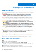
Latitude 7340 Service Manual Regulatory Model: P178G/P179G Regulatory Type: P178G001/P179G001 March 2023 Rev. A00 - Dell Latitude 7340 | Service Manual - Page 2
and tells you how to avoid the problem. WARNING: A WARNING indicates a potential for property damage, personal injury, or death. © 2023 Dell Inc. or its subsidiaries. All rights reserved. Dell Technologies, Dell, and other trademarks are trademarks of Dell Inc. or its subsidiaries. Other trademarks - Dell Latitude 7340 | Service Manual - Page 3
discharge-ESD protection...7 ESD field service kit ...8 Transporting sensitive components...9 After working inside your computer...9 BitLocker...9 Chapter 2: Removing and installing components 10 Recommended tools...10 Screw list...10 Major components of Latitude 7340...11 NanoSIM-card tray...13 - Dell Latitude 7340 | Service Manual - Page 4
the speakers for ultralight...40 Installing the speakers for ultralight...41 Removing the 62 Installing the palm-rest assembly ...63 Chapter 3: Drivers and downloads 65 Chapter 4: BIOS setup...66 Entering Chapter 5: Troubleshooting...82 Handling swollen Lithium-ion batteries...82 Dell SupportAssist - Dell Latitude 7340 | Service Manual - Page 5
)...86 Backup media and recovery options...87 Wi-Fi power cycle...87 Drain residual flea power (perform hard reset)...87 Chapter 6: Getting help and contacting Dell 88 Contents 5 - Dell Latitude 7340 | Service Manual - Page 6
troubleshooting and repairs as authorized or directed by the Dell technical assistance team. Damage due to servicing that is not authorized by Dell is not covered by your warranty. See the safety instructions caution when handling Lithium-ion batteries in laptops. Swollen batteries should not be used - Dell Latitude 7340 | Service Manual - Page 7
Service Mode or the computer does not support Service for 3 seconds or until the Dell logo appears on the screen. service mode skip this process. Safety precautions The safety precautions chapter details the primary steps to be taken before performing any disassembly instructions problems or - Dell Latitude 7340 | Service Manual - Page 8
; a red LED is lit and an alarm sounds if the test fails. ● Insulator Elements - It is critical to keep ESD sensitive devices, such as plastic heat sink casings, away from internal parts that are insulators and often highly charged. ● Working Environment - Before deploying the ESD Field Service kit - Dell Latitude 7340 | Service Manual - Page 9
transport. ESD protection summary It is recommended to use the traditional wired ESD grounding wrist strap and protective anti-static mat at all times when servicing Dell products. In addition, it is critical to keep sensitive parts separate from all insulator parts while performing - Dell Latitude 7340 | Service Manual - Page 10
2 Removing and installing components NOTE: The images in this document may differ from your computer depending on the configuration you ordered. Recommended tools The procedures in this document may require the following tools: ● Phillips screwdriver #0 ● Phillips screwdriver #1 ● Plastic scribe - Dell Latitude 7340 | Service Manual - Page 11
1 4 2 2 4 Screw image Smart-card reader M2x2.5 4 System board M2x4 1 Power button with optional M1.2x1.5 2 fingerprint reader Keyboard M1.2x1.5 29 Major components of Latitude 7340 The following image shows the major components of Latitude 7340. Removing and installing components 11 - Dell Latitude 7340 | Service Manual - Page 12
1. Base cover 3. Heat-sink shield 5. Heat sink 7. System board 12 Removing and installing components 2. Solid-state drive shield 4. Solid-state drive 6. Battery 8. Keyboard bracket - Dell Latitude 7340 | Service Manual - Page 13
. WWAN-card shield 10. Right antenna 12. Palm-rest and keyboard assembly 14. Left antenna 16. WWAN card 18. Fingerprint reader NOTE: Dell provides a list of components and their part numbers for the original system configuration purchased. These parts are available according to warranty coverages - Dell Latitude 7340 | Service Manual - Page 14
Steps 1. Insert a pin into the release hole of the nanoSIM-card tray and push inward until the tray is released. 2. Slide the nanoSIM-card tray out of the slot on the computer. 3. Remove the SIM card from the nanoSIM-card tray. 4. Slide the nanoSIM-card tray into the slot, until it clicks into place - Dell Latitude 7340 | Service Manual - Page 15
Steps 1. Insert a pin into the hole of the nanoSIM-card tray and push inward until the tray is released. 2. Slide the nanoSIM-card tray out of the slot on the computer. 3. Place the SIM card into the nanoSIM-card tray with the metallic contact facing up. 4. Align the nanoSIM-card tray with the slot - Dell Latitude 7340 | Service Manual - Page 16
About this task The following images indicate the location of the base cover and provide a visual representation of the removal procedure. 16 Removing and installing components - Dell Latitude 7340 | Service Manual - Page 17
Steps 1. Loosen the eight captive screws that secure the base cover to the palm-rest and keyboard assembly. 2. Using a plastic scribe, pry open the base cover starting from the recesses, which are located in the U-shaped indents at the top edge of the base cover, near the hinges. CAUTION: Do not - Dell Latitude 7340 | Service Manual - Page 18
3. Pry open the top side of the base cover and continue working on the left, right and, bottom sides to open the base cover. 4. Lift the base cover from the left and right sides and remove the base cover off the palm-rest and keyboard assembly. Installing the base cover Prerequisites If you are - Dell Latitude 7340 | Service Manual - Page 19
Steps 1. Place the base cover on top of the palm-rest and keyboard assembly. 2. Align the screw holes on the base cover with the screw holes on the palm-rest and keyboard assembly, and snap the base cover latches into place. 3. Tighten the eight captive screws to secure the base cover to the palm- - Dell Latitude 7340 | Service Manual - Page 20
on state. 2. Remove the base cover. About this task NOTE: The M.2 card that is installed on your computer depends on the configuration ordered. Supported card configurations on the M.2 card slot are: ● M.2 2230 solid-state drive The following image indicates the location of the M.2 2230 solid-state - Dell Latitude 7340 | Service Manual - Page 21
. c. If you have replaced the primary storage device that had the operating system installed, search in the Knowledge Base Resource at www.dell.com/support. Wireless Wide Area Network (WWAN) card Removing the 5G WWAN card Prerequisites 1. Follow the procedure in Before working inside your computer - Dell Latitude 7340 | Service Manual - Page 22
About this task NOTE: This procedure applies only to computers shipped with a 5G WWAN card installed. NOTE: WWAN card is configured at point of sales for 2-in-1 computers, WWAN card upgrade (CUS Kit) is not available for 2-in-1 computers. The following images indicate the location of the 5G WWAN - Dell Latitude 7340 | Service Manual - Page 23
Installing the 5G WWAN card Prerequisites If you are replacing a component, remove the existing component before performing the installation procedure. About this task The following images indicate the location of the 5G WWAN card and provide a visual representation of the installation procedure. - Dell Latitude 7340 | Service Manual - Page 24
instructions on how to find your computer's International Mobile Station Equipment Identity (IMEI) number, search in the Knowledge Base Resource at www.dell.com/support on or against the battery. ● Ensure any screws during the servicing of this product are not lost or misplaced, to prevent accidental - Dell Latitude 7340 | Service Manual - Page 25
Steps 1. Use the pull tab to disconnect the battery cable from the connector on the system board. 2. Loosen the five captive screws that secures the 2-cell battery to the palm-rest and keyboard assembly. 3. Lift the 2-cell battery along with the battery cable off the palm-rest and keyboard assembly. - Dell Latitude 7340 | Service Manual - Page 26
Steps 1. Carefully push the battery filler upwards to attach it to the 2-cell battery. 2. Place the 2-cell battery along with the battery cable on the palm-rest and keyboard assembly. 3. Align the screw holes on the 2-cell battery to the screw holes on the palm-rest and keyboard assembly. 4. Tighten - Dell Latitude 7340 | Service Manual - Page 27
About this task The following image indicates the location of the 3-cell battery and provides a visual representation of the removal procedure. Steps 1. Disconnect the battery cable from the connector on the system board, if it was not disconnected earlier. 2. Loosen the five captive screws that - Dell Latitude 7340 | Service Manual - Page 28
the base cover. 3. Remove the 2-cell battery or the3-cell battery, whichever is applicable. NOTE: If battery is disconnected from system board for service, then there is a delay during system boot as the system undergoes RTC battery reset. About this task The following images indicate the location - Dell Latitude 7340 | Service Manual - Page 29
Steps 1. Flip the battery and unroute the battery cable from the routing guides on the battery. 2. Disconnect the battery cable from the connector on the battery. 3. Lift the battery cable away from the battery. NOTE: Dummy filler for a 2- - Dell Latitude 7340 | Service Manual - Page 30
Steps 1. Connect the battery cable to the connector on the battery. 2. Route the battery cable through the routing guides on the battery. Next steps 1. Install the 2-cell battery or the3-cell battery, whichever is applicable. 2. Install the base cover. 3. Follow the procedure in After - Dell Latitude 7340 | Service Manual - Page 31
) securing WLAN and WWAN brackets from the system board. 2. Disconnect the cables from the connector and release the cables from the cable routing guides. 3. Remove the single screw (M2x4) securing a fan. 4. Disconnect the thermal-fan cable from the connector on the system board. 5. Lift and remove - Dell Latitude 7340 | Service Manual - Page 32
thermal-fan cable to the connector on the system board. 5. Connect the cables to the connector and place the cables to the cable routing guides. 6. Replace three screws (M2x3) securing WLAN and WWAN brackets on the system board. Next steps 1. Install the base cover. 2. Follow the procedure in After - Dell Latitude 7340 | Service Manual - Page 33
Steps 1. Remove the single screw (M2x3) to open the SSD shielding cover from the system board. 2. Peel back the tape that secures the thermal module. 3. Remove the to the system board. 4. In reverse sequential order (as indicated on the heat-sink), loosen the four captive screws that secure the heat - Dell Latitude 7340 | Service Manual - Page 34
NOTE: Incorrect alignment of the heat-sink can damage the system board and processor. The following image indicates the location of the heat-sink and provides a visual representation of the installation procedure. Steps 1. Place the heat-sink on the system board. 2. Align the screw holes on the - Dell Latitude 7340 | Service Manual - Page 35
procedure. Steps 1. Disconnect the coin-cell battery cable from the connector on the system board. 2. Unroute the coin-cell battery cable from the routing guides on the system board. 3. Using a plastic scribe, pry the coin-cell battery off its slot on the system board. Installing the coin-cell - Dell Latitude 7340 | Service Manual - Page 36
Steps 1. Place the coin-cell battery into its slot on the system board. 2. Route the coin-cell battery cable back to the routing guides on the system board. 3. Connect the coin-cell battery cable to the connector on the system board. Next steps 1. Install the base cover. 2. Follow the - Dell Latitude 7340 | Service Manual - Page 37
Removing and installing components 37 - Dell Latitude 7340 | Service Manual - Page 38
Steps 1. Remove the two screws (M2x3) securing the EDP cable bracket on the system board. 2. Remove the two screws (M2x3) securing the camera cable bracket on the system board. 3. Disconnect and peel off the camera cable and display cable from the system board. 4. Remove the four screws (M2.5x5) - Dell Latitude 7340 | Service Manual - Page 39
Removing and installing components 39 - Dell Latitude 7340 | Service Manual - Page 40
WWAN card installed. 2. Install the base cover. 3. Follow the procedure in After working inside your computer. Speakers Removing the speakers for ultralight Prerequisites 1. Follow the procedure in Before working inside your computer. 2. Remove the base cover. 3. Remove the WWAN card. 40 Removing - Dell Latitude 7340 | Service Manual - Page 41
Note the speaker cable routing, and unroute the speaker cable from the routing guides on the palm-rest and keyboard assembly. 5. Lift the speakers, along the palm-rest and keyboard assembly. Installing the speakers for ultralight Prerequisites If you are replacing a component, remove the existing - Dell Latitude 7340 | Service Manual - Page 42
assembly. 3. Route the speaker cable along the bottom side of the palm-rest and keyboard assembly. Then secure the speaker cable into the routing guides on the palm-rest and keyboard assembly. 4. Connect the speaker cable to the connector on the I/O daughter-board. Next steps 1. Install the base - Dell Latitude 7340 | Service Manual - Page 43
that secures the speaker cable to the palm-rest and keyboard assembly. 3. Note the speaker cable routing, and unroute the speaker cable from the routing guides on the palm-rest and keyboard assembly. 4. Lift the speakers, along with the cable, off the palm-rest and keyboard assembly. Installing the - Dell Latitude 7340 | Service Manual - Page 44
assembly. 2. Route the speaker cable along the bottom side of the palm-rest and keyboard assembly. Then secure the speaker cable into the routing guides on the palm-rest and keyboard assembly. 3. Connect the speaker cable to the connector on the I/O daughter-board. Next steps 1. Install the base - Dell Latitude 7340 | Service Manual - Page 45
Steps 1. Open the latch and disconnect the clickpad flexible flat cable from the connector on the clickpad. 2. Remove the four screws (M2x2.5)(M2x2) that secure the smart card reader to the palm-rest and keyboard assembly. 3. Remove the smart card reader from the computer. Installing the smart card - Dell Latitude 7340 | Service Manual - Page 46
Steps 1. Align and place the smart card reader on the palm-rest and keyboard assembly. 2. Replace the four screws (M2x2.5)(M2x2) that secure the smart card reader to the palm-rest and keyboard assembly. 3. Connect the clickpad flexible flat cable to the connectors on the clickpad. Next steps 1. - Dell Latitude 7340 | Service Manual - Page 47
1. Fingerprint reader 2. Darwin 1 antenna cable 3. Darwin 2 antenna cable 4. P sensor connector 5. LCD connector 6. IR-camera cable connector 7. M.2 solid-state drive connector 8. Battery cable connector 9. Speaker 2 10. Fan connector 11. Clickpad FFC connector 12. WLAN 13. USH daughter-board FFC - Dell Latitude 7340 | Service Manual - Page 48
Steps 1. Remove the six screws (M2x3) securing the display, camera, and USB Type-C brackets. 2. Disconnect camera and display cables on the system board. 3. Disconnect the camera cable, display cable, battery cable, speaker cable, clickpad flexible flat cable, USH daughter board flexible flat cable - Dell Latitude 7340 | Service Manual - Page 49
NOTE: There are 2 speaker cables to disconnect. 4. Remove the single screw (M2x4) securing the system board in place. 5. Remove the system board from the system. 6. Carefully lift and remove the system board away from the palm-rest and keyboard assembly. NOTE: Transfer the re-useable WLAN, WWAN (for - Dell Latitude 7340 | Service Manual - Page 50
NOTE: For the systems supporting 5G configuration, the CPU absorber sticker adhered to the system board must be peeled off and transferred over to the replacement system board. CPU absorber - Dell Latitude 7340 | Service Manual - Page 51
1. Fingerprint reader 2. Darwin 1 antenna cable 3. Darwin 2 antenna cable 4. P sensor connector 5. LCD connector 6. IR-camera cable connector 7. M.2 solid-state drive connector 8. Battery cable connector 9. Speaker 2 10. Fan connector 11. Clickpad FFC connector 12. WLAN 13. USH daughter-board FFC - Dell Latitude 7340 | Service Manual - Page 52
Steps 1. Place the system board into the respective slot on the palm-rest and keyboard assembly. NOTE: Transfer the reusable WLAN absorbers to the new system board while replacing the system board. 2. Replace the single screw (M2x4) securing the system board in place. 52 Removing and installing - Dell Latitude 7340 | Service Manual - Page 53
3. Connect the camera cable, display cable, battery cable, speaker cable, clickpad flexible flat cable, USH daughter board flexible flat cable (for models shipped with a USH daughter board), RTC cable, finger print reader power button cable, Darwin cables, and P cable, on the system board. 4. - Dell Latitude 7340 | Service Manual - Page 54
the WLAN-antenna module bracket to the system board. 2. Unroute the white WLAN Main antenna cable and black WLAN Aux antenna cable from the routing guides on the palm rest. 3. Slide and remove the WLAN-antenna module from the WLAN-antenna module slot on the system board. Installing the WLAN-antenna - Dell Latitude 7340 | Service Manual - Page 55
Slide and replace the WLAN-antenna module to the WLAN-antenna module slot on the system board. 2. Route the WLAN-antenna cables from the routing guides on the system board. 3. Replace the four screws (M2x2.5) that secure the WLAN-antenna module bracket on the system board. Next steps 1. Install the - Dell Latitude 7340 | Service Manual - Page 56
NOTE: For computers shipped with a fingerprint reader, the power button includes a fingerprint reader module. The following images indicate the location of the power button with optional fingerprint reader and provide a visual representation of the removal procedure. Steps 1. Remove the two screws - Dell Latitude 7340 | Service Manual - Page 57
Steps 1. Place the power button into its slot on the palm-rest and keyboard assembly. 2. Adhere the fingerprint reader flexible printed circuits to the connector on the palm-rest and keyboard assembly. NOTE: This step applies only to computers shipped with a power button with fingerprint reader - Dell Latitude 7340 | Service Manual - Page 58
7. Remove the speakers. 8. Remove the Power button. 9. Remove the system board. NOTE: When removing the system board to replace or access other parts, the system board can be removed and installed with the heat sink attached to simplify the procedure and preserve the thermal bond between the system - Dell Latitude 7340 | Service Manual - Page 59
assembly to the system. 4. Carefully lift the keyboard assembly to remove it from the computer. 5. Separate the keyboard from the keyboard support plate. NOTE: If the keyboard support plate is replaced, transfer the re-useable rubber filler (for WLAN, 4G WWAN) or thermal pad (for 5G WWAN) over to - Dell Latitude 7340 | Service Manual - Page 60
No Keyboard Support Plate for 5G WWAN Components 1 Thermal pad for 5G WWAN Installing the keyboard Prerequisites If you are replacing a component, remove the existing component before performing - Dell Latitude 7340 | Service Manual - Page 61
Steps 1. Align the screw holes on the keyboard to the screw holes on the keyboard support plate and place the keyboard on the keyboard support plate. 2. Align and place the keyboard assembly in to its slot in the computer. 3. Replace the twenty-nine screws (M1.2x1.5) securing the keyboard assembly - Dell Latitude 7340 | Service Manual - Page 62
4. Connect the keyboard and keyboard backlight flat cable to the back of the clickpad. 5. Adhere the USH daughter-board flexible flat cable to the back of the keyboard. NOTE: This step applies only to computers shipped with a USH daughter-board installed. Next steps 1. Follow the procedure in Before - Dell Latitude 7340 | Service Manual - Page 63
Steps 1. For computers shipped with a carbon fiber palm-rest, use a fine-tipped instrument to push the nanoSIM outwards to remove it from its slot on the palm-rest assembly. 2. After performing the pre-requisites, you are left with the palm-rest assembly. Installing the palm-rest assembly - Dell Latitude 7340 | Service Manual - Page 64
Steps 1. For computers shipped with a carbon fiber palm-rest, align to the slot on the palm-rest assembly. 2. Place the palm-rest assembly on a flat surface and perform the post-requisites to install the palm-rest assembly. Next steps 1. Install the keyboard. 2. Install the power button. 3. Install - Dell Latitude 7340 | Service Manual - Page 65
3 Drivers and downloads When troubleshooting, downloading or installing drivers it is recommended that you read the Dell Knowledge Base article, Drivers and Downloads FAQ 000123347. Drivers and downloads 65 - Dell Latitude 7340 | Service Manual - Page 66
4 BIOS setup CAUTION: Unless you are an expert computer user, do not change the settings in the BIOS Setup program. Certain changes can make your computer work incorrectly. NOTE: Depending on the computer and its installed devices, the items listed in this section may or may not be displayed. NOTE - Dell Latitude 7340 | Service Manual - Page 67
options-System information menu Overview Latitude 7340 BIOS Version Displays the BIOS version number. Service Tag Displays the Service Tag of the system. Asset the ownership date of the system. Express Service Code Displays the express service code of the system. Ownership Tag Displays the - Dell Latitude 7340 | Service Manual - Page 68
Table 3. System setup options-System information menu (continued) Overview 64-Bit Technology Displays whether 64-bit technology is used. Memory Information Memory Installed Displays the total system memory installed. Memory Available Displays the total system memory available. Memory Speed - Dell Latitude 7340 | Service Manual - Page 69
Preboot. By default, the Enable Thunderbolt Boot Support option is disabled. Enable Thunderbolt (and PCIe is disabled. Type-C Dock Override Enables to use connected Type-C Dell Dock to provide data stream with external USB ports disabled. When light and sound. By default, the Enable Unobtrusive Mode - Dell Latitude 7340 | Service Manual - Page 70
or disable the internal Contactless smart card/NFC device. By default, the option enabled. NOTE: This option is available only for systems that support Contactless smart card/NFC. Enable UEFI Network Stack Enable or disable UEFI Network Stack and controls the on-board LAN Controller. By default - Dell Latitude 7340 | Service Manual - Page 71
With Auto Mode, the HTTPs Boot extracts Boot URL from the DHCP. With Manual Mode, the HTTPs Boot reads Boot URL from the user-provided data. By default the Optimized option is enabled. USB Wake Support Wake on Dell USB-C Dock When enabled, connecting a Dell USB-C Dock will wake the system from - Dell Latitude 7340 | Service Manual - Page 72
option is enabled. Intel Speed Shift Technology Enable or disable the Intel speed shift technology support. By default, the Intel Speed Shift Technology option is enabled. Table 10. System setup interface of the optional Absolute Persistence Module service from Absolute software. 72 BIOS setup - Dell Latitude 7340 | Service Manual - Page 73
Table 10. System setup options-Security menu (continued) Security By default, the option is enabled. WARNING: The 'Permanently Disabled' option can only be selected once. When 'Permanently Disabled' is selected, Absolute Persistence cannot be re-enabled. No further changes to the Enable/Disable - Dell Latitude 7340 | Service Manual - Page 74
enabled, this disables the master password support. By default, the option is disabled PSID) revert of NVMe hard-drives from the Dell Security Manager prompt. By default, the option is certain system errors. By default, the option is enabled. BIOSConnect Enable or disable cloud Service operating - Dell Latitude 7340 | Service Manual - Page 75
option is enabled. With this option, the F1-F2 keys scan the code for their secondary functions. Enables to change the keyboard illumination settings. By and Errors Enable or disable the action to be done when a warning or error is encountered. By default, the Prompt on Warnings and Errors option - Dell Latitude 7340 | Service Manual - Page 76
Technology. The following must be enabled in order to enable Intel TXT. ● Trusted Platform Module (TPM) ● Intel Hyper-Threading ● All CPU cores (Multi-Core Support) ● Intel Virtualization Technology ● Intel VT for Direct I/O By default, the option is disabled. DMA Protection Enable Pre-Boot DMA - Dell Latitude 7340 | Service Manual - Page 77
Search support box, enter the Service Tag of your computer, and then click Search. NOTE: If you do not have the Service Tag, use the SupportAssist feature to automatically identify your computer. You can also use the product ID or manually browse for your computer model. 3. Click Drivers & Downloads - Dell Latitude 7340 | Service Manual - Page 78
you saved the BIOS update file. 8. Double-click the BIOS update file icon and follow the on-screen instructions. For more information, search in the Knowledge Base Resource at www.dell.com/support. Updating the BIOS in Linux and Ubuntu To update the system BIOS on a computer that is installed with - Dell Latitude 7340 | Service Manual - Page 79
following: ● USB drive formatted to the FAT32 file system (key does not have to be bootable) ● BIOS executable file that you downloaded from the Dell Support website and copied to the root of the USB drive ● AC power adapter that is connected to the computer ● Functional computer battery to flash - Dell Latitude 7340 | Service Manual - Page 80
● At least one special character Numbers 0 through 9. ● Upper case letters from A to Z. ● Lower case letters from a to z. 3. Type the system password that you entered earlier in the Confirm new password field and click OK. 4. Press Esc and save the changes as prompted by the pop-up message. 5. - Dell Latitude 7340 | Service Manual - Page 81
Clearing BIOS (System Setup) and System passwords About this task To clear the system or BIOS passwords, contact Dell technical support as described at www.dell.com/contactdell. NOTE: For information on how to reset Windows or application passwords, refer to the documentation accompanying Windows or - Dell Latitude 7340 | Service Manual - Page 82
. Contact Dell product support at https://www.dell.com/support for assistance and further instructions. ● Using a non-Dell or incompatible laptop battery and to minimize the possibility of occurrence of the issue, search Dell Laptop Battery in the Knowledge Base Resource at www.dell.com/support. Dell - Dell Latitude 7340 | Service Manual - Page 83
Run Tests. 8. If there are any issues, error codes are displayed. Note the error code and validation number and contact Dell. Built-in self-test (BIST) M- status LED will flash one of the following error codes for 30 seconds: Table 20. LED error codes Blinking Pattern Possible Problem Amber - Dell Latitude 7340 | Service Manual - Page 84
For cases when a [2,8] error code is shown, replace the system board. LCD Built-in Self Test (BIST) Dell laptops have a built-in diagnostic tool that helps you determine if the screen abnormality you are experiencing is an inherent problem with the LCD (screen) of the Dell laptop or with the video - Dell Latitude 7340 | Service Manual - Page 85
all for ungraceful EC code flow errors Suggested resolution Disconnect all power source (AC, battery, coin cell) and drain flea power by pressing and holding down power button for 3-5 seconds. CPU failure ● Run the Dell Support Assist/Dell Diagnostics tool. ● If problem persists, replace the - Dell Latitude 7340 | Service Manual - Page 86
BIOS recovery from USB", and the instructions are in the website Dell support. ● If problem persists, replace the system board. issues, repair your computer, back up your files, or restore your computer to its factory state. You can also download it from the Dell Support website to troubleshoot - Dell Latitude 7340 | Service Manual - Page 87
options It is recommended to create a recovery drive to troubleshoot and fix problems that may occur with Windows. Dell proposes multiple options for recovering Windows operating system on your Dell PC. For more information. see Dell Windows Backup Media and Recovery Options. Wi-Fi power cycle - Dell Latitude 7340 | Service Manual - Page 88
, drivers and downloads, and learn more about your computer through videos, manuals and documents. Your Dell computer is uniquely identified by a Service Tag or Express Service Code. To view relevant support resources for your Dell computer, enter the Service Tag or Express Service Code at www.dell
-
 1
1 -
 2
2 -
 3
3 -
 4
4 -
 5
5 -
 6
6 -
 7
7 -
8
-
9
-
10
-
11
-
12
-
13
-
14
-
15
-
16
-
17
-
18
-
19
-
20
-
21
-
22
-
23
-
24
-
25
-
26
-
27
-
28
-
29
-
30
-
31
-
32
-
33
-
34
-
35
-
36
-
37
-
38
-
39
-
40
-
41
-
42
-
43
-
44
-
45
-
46
-
47
-
48
-
49
-
50
-
51
-
52
-
53
-
54
-
55
-
56
-
57
-
58
-
59
-
60
-
61
-
62
-
63
-
64
-
65
-
66
-
67
-
68
-
69
-
70
-
71
-
72
-
73
-
74
-
75
-
76
-
77
-
78
-
79
-
80
-
81
-
82
-
83
-
84
-
85
-
86
-
87
-
88
 |
 |

Latitude 7340
Service Manual
Regulatory Model: P178G/P179G
Regulatory Type: P178G001/P179G001
March 2023
Rev. A00