Dell OptiPlex 7070 Tower Service Manual
Dell OptiPlex 7070 Tower Manual
 |
View all Dell OptiPlex 7070 Tower manuals
Add to My Manuals
Save this manual to your list of manuals |
Dell OptiPlex 7070 Tower manual content summary:
- Dell OptiPlex 7070 Tower | Service Manual - Page 1
OptiPlex 7070 Tower Service Manual Regulatory Model: D18M Regulatory Type: D18M005 September 2021 Rev. A02 - Dell OptiPlex 7070 Tower | Service Manual - Page 2
data and tells you how to avoid the problem. WARNING: A WARNING indicates a potential for property damage, personal injury, or death. © 2019-2021 Dell Inc. or its subsidiaries. All rights reserved. Dell, EMC, and other trademarks are trademarks of Dell Inc. or its subsidiaries. Other trademarks may - Dell OptiPlex 7070 Tower | Service Manual - Page 3
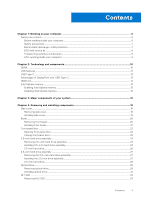
Contents Chapter 1: Working on your computer 6 Safety instructions...6 Before working inside your computer...6 Safety precautions...7 Electrostatic discharge-ESD protection...7 ESD field service kit ...8 Transporting sensitive components...9 After working inside your computer...9 Chapter 2: - Dell OptiPlex 7070 Tower | Service Manual - Page 4
Installing M.2 SSD...34 SD card reader...35 Removing SD card reader...35 Installing SD card reader...36 Memory module...37 Removing memory module...37 Installing memory module...38 Expansion card...39 Removing PCIe expansion card...39 Installing PCIe expansion card...40 Power supply unit...41 - Dell OptiPlex 7070 Tower | Service Manual - Page 5
...76 Post behavior...77 Manageability...78 Virtualization support...78 Wireless options...78 Maintenance...78 System BIOS (System Setup) and System passwords 82 Chapter 6: Troubleshooting...83 Enhanced Pre-Boot System Assessment - ePSA diagnostics 83 Running Contacting Dell...91 Contents 5 - Dell OptiPlex 7070 Tower | Service Manual - Page 6
troubleshooting and simple repairs as authorized in your product documentation, or as directed by the online or telephone service and support team. Damage due to servicing that is not authorized by Dell is not covered by your warranty. Read and follow the safety instructions , and monitor from your - Dell OptiPlex 7070 Tower | Service Manual - Page 7
disassembly instructions. electrocuted. Standby power Dell products with standby power done through the use of a field service electrostatic discharge (ESD) kit. When obvious, such as intermittent problems or a shortened product life of damage to recognize and troubleshoot is the intermittent (also - Dell OptiPlex 7070 Tower | Service Manual - Page 8
for safe transport. ESD protection summary It is recommended that all field service technicians use the traditional wired ESD grounding wrist strap and protective anti-static mat at all times when servicing Dell products. In addition, it is critical that technicians keep sensitive parts separate - Dell OptiPlex 7070 Tower | Service Manual - Page 9
such as replacement parts or parts to be returned to Dell, it is critical to place these parts in anti-static apart for a stable base, and point your toes out. 2. Tighten stomach muscles. Abdominal muscles support your spine when you lift, offsetting the force of the load. 3. Lift with your legs, - Dell OptiPlex 7070 Tower | Service Manual - Page 10
memory into the system. DDR4 needs 20 percent less or just 1.2 volts, compared to DDR3 which requires 1.5 volts of electrical power to operate. DDR4 also supports a new, deep power-down mode that allows the host device to go into standby without needing to refresh its memory. Deep power-down mode is - Dell OptiPlex 7070 Tower | Service Manual - Page 11
on the system display the new ON-FLASH-FLASH or ON-FLASH-ON failure code. If all memory fails, the LCD does not turn on. Troubleshoot for possible memory failure by trying known good memory modules in the memory connectors on the bottom of the system or under the keyboard, as - Dell OptiPlex 7070 Tower | Service Manual - Page 12
● Full-duplex data transfers and support for new transfer types ● Backward USB 2.0 compatibility ● New connectors and cable The topics below cover some of the most commonly asked questions regarding USB 3.0/USB 3.1 - Dell OptiPlex 7070 Tower | Service Manual - Page 13
size of an old USB Type-A plug. This is a single connector standard that every device should be able to use. USB Type-C ports can support a variety of different protocols using "alternate modes," which allows you to have adapters that can output HDMI, VGA, DisplayPort, or other types of connections - Dell OptiPlex 7070 Tower | Service Manual - Page 14
player, or A/V receiver and a compatible digital audio and/or video monitor, such as a digital TV (DTV). The intended applications for HDMI memory (RAM) installed on your computer. NOTE: Intel Optane memory is supported on computers that meet the following requirements: ● 7th Generation or higher - Dell OptiPlex 7070 Tower | Service Manual - Page 15
Table 2. Intel Optane memory specifications Feature Interface Connector Configurations supported Capacity Specifications PCIe 3x2 NVMe 1.1 M.2 card slot (2230/2280) ● 7th Generation or higher Intel Core i3/i5/i7 processor ● Windows 10 64-bit version 1607 - Dell OptiPlex 7070 Tower | Service Manual - Page 16
3 Major components of your system 1. Side cover 2. 3.5-inch hard drive assembly 3. Optical drive 4. Heatsink assembly 5. Processor 6. Memory module 7. M.2 SSD 8. SD card reader 9. Power button 10. System board 11. Front panel door 12. Bezel 13. 2.5-inch hard drive assembly 14. Speaker 15. System - Dell OptiPlex 7070 Tower | Service Manual - Page 17
NOTE: Dell provides a list of components and their part numbers for the original system configuration purchased. These parts are available according to warranty coverages purchased by the customer. Contact your Dell sales representative for purchase options. Major components of your system 17 - Dell OptiPlex 7070 Tower | Service Manual - Page 18
4 Removing and installing components NOTE: The images in this document may differ from your computer depending on the configuration you ordered. Topics: • Side cover • Bezel • Front panel door • 3.5-inch hard drive assembly • 2.5-inch hard drive assembly • Optical drive • M.2 SSD • SD card reader • - Dell OptiPlex 7070 Tower | Service Manual - Page 19
Installing side cover 1. To install the side cover: a. The release latch automatically locks the side cover to the system [2]. Removing and installing components 19 - Dell OptiPlex 7070 Tower | Service Manual - Page 20
2. Follow the procedure in After working inside your computer. Bezel Removing front bezel 1. Follow the procedure in Before working inside your computer. 2. Remove the Side cover. 3. To remove the front bezel: a. Pry the retention tabs to release the front bezel from the system [1]. b. Rotate the - Dell OptiPlex 7070 Tower | Service Manual - Page 21
Installing front bezel 1. To install the front bezel: a. Position the bezel to align the tab holders with the slots on the system chassis. b. Press the bezel until the tabs click into place. 2. Install the Side cover. 3. Follow the procedure in After working inside your computer. Removing and - Dell OptiPlex 7070 Tower | Service Manual - Page 22
Front panel door Opening front panel door 1. Follow the procedure in Before working inside your computer. 2. Remove the: a. Side cover b. Front bezel CAUTION: The front panel door opens only to a limited extent. See the printed image on the front panel door for the maximum permissible level. 3. Pull - Dell OptiPlex 7070 Tower | Service Manual - Page 23
2. Install the: a. Front bezel b. Side cover 3. Follow the procedure in After working inside your computer. 3.5-inch hard drive assembly Removing 3.5-inch hard drive assembly 1. Follow the procedure in Before working inside your computer. 2. Remove the: a. Side cover b. Front bezel 3. To remove the - Dell OptiPlex 7070 Tower | Service Manual - Page 24
b. Remove the HDD filler bracket from the system [1]. c. Press the blue tab [2] and pull the hard drive assembly out of the system [3]. Installing 3.5-inch hard drive assembly 1. Insert the hard drive assembly into the slot on the system until it clicks into place [1]. 2. Replace the HDD filler - Dell OptiPlex 7070 Tower | Service Manual - Page 25
3. Connect the SATA cable and the power cable to the connectors on the hard drive. 4. Install the: a. Front bezel b. Side cover 5. Follow the procedure in After working inside your computer. Removing and installing components 25 - Dell OptiPlex 7070 Tower | Service Manual - Page 26
3.5-inch hard drive Removing 3.5-inch hard drive from the hard drive bracket 1. Follow the procedure in Before working inside your computer. 2. Remove the: a. Side cover b. Front bezel c. 3.5-inch HDD assembly 3. To remove the hard drive : a. Pull one side of the hard drive bracket to disengage the - Dell OptiPlex 7070 Tower | Service Manual - Page 27
2.5-inch hard drive assembly Removing the 2.5-inch hard drive assembly 1. Follow the procedure in Before working inside your computer. 2. Remove the: a. Side cover b. Front bezel 3. Open the front panel door. 4. To remove the hard drive assembly: a. Disconnect the hard drive data and power cables - Dell OptiPlex 7070 Tower | Service Manual - Page 28
2. Close the front panel door. 3. Install the: a. Front bezel b. Side cover 4. Follow the procedure in After Working Inside Your Computer. 2.5-inch hard drive Removing the 2.5-inch drive from the drive bracket 1. Follow the procedure in Before Working Inside Your Computer. 2. Remove the: a. Side - Dell OptiPlex 7070 Tower | Service Manual - Page 29
Installing the 2.5-inch hard drive into the hard drive bracket 1. To install the hard drive: a. Align the hard drive to the side of the hard drive bracket, and pull the other end tabs to insert the pins on the bracket into the hard drive. b. Insert the hard drive into the hard drive bracket until it - Dell OptiPlex 7070 Tower | Service Manual - Page 30
c. Press the blue release tab [1] and slide the optical drive out of the system [2]. 30 Removing and installing components - Dell OptiPlex 7070 Tower | Service Manual - Page 31
Installing optical drive 1. To install the optical drive: a. Insert the optical drive into the optical drive bay until it clicks into place [1]. b. Open the front panel door [2]. Removing and installing components 31 - Dell OptiPlex 7070 Tower | Service Manual - Page 32
c. Route the cables under the drive cage. d. Connect the optical drive data cable and power cable to the connectors on the optical drive [1] . e. Close the front panel door [2]. 32 Removing and installing components - Dell OptiPlex 7070 Tower | Service Manual - Page 33
2. Install the: a. Front bezel b. Side cover 3. Follow the procedure in After working inside your computer. M.2 SSD Removing M.2 SSD 1. Follow the procedure in Before working inside your computer. 2. Remove the: a. Side cover b. Front bezel 3. Open the front panel door. 4. To remove the M.2 SSD: a. - Dell OptiPlex 7070 Tower | Service Manual - Page 34
Installing M.2 SSD 1. Insert the M.2 SSD to the connector on the system board [1]. 2. Replace the single screw to secure the SSD to the system board [2]. 34 Removing and installing components - Dell OptiPlex 7070 Tower | Service Manual - Page 35
3. Close the front panel door. 4. Install the: a. Front bezel b. Side cover 5. Follow the procedure in After working inside your computer. SD card reader Removing SD card reader 1. Follow the procedure in Before working inside your computer. 2. Remove the: a. Side cover b. Front bezel 3. Open the - Dell OptiPlex 7070 Tower | Service Manual - Page 36
Installing SD card reader 1. To install the SD card reader: a. Insert the SD card reader into the slot on the front panel door [1]. b. Replace the screw to secure the SD card reader to the front panel door [2]. c. Connect the SD card reader cable to the connector on the system board [3]. 36 - Dell OptiPlex 7070 Tower | Service Manual - Page 37
2. Close the front panel door. 3. Install the: a. Front bezel b. Side cover 4. Follow the procedure in After working inside your computer. Memory module Removing memory module 1. Follow the procedure in Before working inside your computer. 2. Remove the: a. Side cover b. Front bezel 3. Open the - Dell OptiPlex 7070 Tower | Service Manual - Page 38
Installing memory module 1. To install the memory module: a. Align the notch on the memory module with the tab on the memory module connector. b. Insert the memory module into the memory module socket [1]. c. Press the memory module until the memory module retention tabs click into place [2]. 38 - Dell OptiPlex 7070 Tower | Service Manual - Page 39
2. Close the front panel door. 3. Install the: a. Front bezel b. Side cover 4. Follow the procedure in After working inside your computer. Expansion card Removing PCIe expansion card 1. Follow the procedure in Before working inside your computer. 2. Remove the: a. Side cover b. Front bezel 3. Open - Dell OptiPlex 7070 Tower | Service Manual - Page 40
5. Repeat the steps to remove any additional PCIe expansion card. Installing PCIe expansion card 1. To install the PCIe expansion card: a. NOTE: To remove the PCIe brackets (2 and 3), push the bracket upwards from the inside of your computer to release it and then lift the bracket away from - Dell OptiPlex 7070 Tower | Service Manual - Page 41
2. Close the front panel door. 3. Install the: a. Front bezel b. Side cover 4. Follow the procedure in After working inside your computer. Power supply unit Removing power supply unit or PSU 1. Follow the procedure in Before working inside your computer. 2. Remove the: a. Side cover b. Front bezel - Dell OptiPlex 7070 Tower | Service Manual - Page 42
5. To remove the PSU: a. Remove the 3 screws that secure the PSU to the system [1]. b. Press the release tab [2]. c. Slide and lift the PSU away from the computer [3]. 42 Removing and installing components - Dell OptiPlex 7070 Tower | Service Manual - Page 43
Installing power supply unit or PSU 1. To install the PSU: a. Insert the PSU into the PSU slot and slide it towards the back of the system until it clicks into place [1]. b. Replace the three screws to secure the PSU to the computer [3]. Removing and installing components 43 - Dell OptiPlex 7070 Tower | Service Manual - Page 44
c. Connect the PSU cables to the connectors on the system board [1]. d. Route the PSU cables through the retention clips [2, 3, 4, 5]. e. Connect the PSU cable to the connector on the system board [6]. 44 Removing and installing components - Dell OptiPlex 7070 Tower | Service Manual - Page 45
2. Close the front panel door. 3. Install the: a. Front bezel b. Side cover 4. Follow the procedure in After working inside your computer. Intrusion switch Removing intrusion switch 1. Follow the procedure in Before working inside your computer. 2. Remove the: a. Side cover b. Front bezel 3. Open - Dell OptiPlex 7070 Tower | Service Manual - Page 46
Installing intrusion switch 1. Insert the intrusion switch into the slot on the system [1]. 2. Route the intrusion switch cable through the fan grommet [2]. 3. Connect the intrusion switch cable to the connector on the system board [3]. 46 Removing and installing components - Dell OptiPlex 7070 Tower | Service Manual - Page 47
4. Close the front panel door. 5. Install the: a. Front bezel b. Side cover 6. Follow the procedure in After working inside your computer. Power button Removing power button 1. Follow the procedure in Before working inside your computer. 2. Remove the: a. Side cover b. Front bezel 3. Open the front - Dell OptiPlex 7070 Tower | Service Manual - Page 48
5. Pull the power button out from the computer. Installing power button 1. Insert the power switch into the slot from the front of the computer and press it until it clicks into place [1]. 2. Open the front panel door [2] 48 Removing and installing components - Dell OptiPlex 7070 Tower | Service Manual - Page 49
3. Route the power switch cable from the power button through the retention clip [2]. 4. Align the cable with the pins on the connector and connect the power button cable [3]. Removing and installing components 49 - Dell OptiPlex 7070 Tower | Service Manual - Page 50
5. Close the front panel door. 6. Install the: a. Front bezel b. Side cover 7. Follow the procedure in After working inside your computer. Speaker Removing speaker 1. Follow the procedure in Before working inside your computer. 2. Remove the: a. Side cover b. Front bezel 3. Open the front panel door - Dell OptiPlex 7070 Tower | Service Manual - Page 51
Installing speaker 1. Insert the speaker into the slot and press it until it clicks into place [1, 2]. 2. Connect the speaker cable to the connector on the system board [2, 3]. Removing and installing components 51 - Dell OptiPlex 7070 Tower | Service Manual - Page 52
3. Close the front panel door. 4. Install the: a. Front bezel b. Side cover 5. Follow the procedure in After working inside your computer. Coin cell battery Removing coin cell battery 1. Follow the procedure in Before working inside your computer. 2. Remove the: a. Side cover b. Front bezel 3. Open - Dell OptiPlex 7070 Tower | Service Manual - Page 53
NOTE: Removing the coin cell battery may reset the system board BIOS/Settings Installing the coin cell battery 1. Hold the coin cell battery with the "+" sign facing up and slide it under the securing tabs at the positive side of the connector [1]. 2. Press the battery into the connector until it - Dell OptiPlex 7070 Tower | Service Manual - Page 54
3. Close the front panel door. 4. Install the: a. Front bezel b. Side cover 5. Follow the procedure in After working inside your computer. Heat sink fan Removing heat sink fan 1. Follow the procedure in Before working inside your computer. 2. Remove the: a. Side cover b. Front bezel 3. Open the - Dell OptiPlex 7070 Tower | Service Manual - Page 55
Installing heatsink fan 1. Place the fan on the heatsink assembly [1]. 2. Tighten the screws (4) to secure the fan to the heatsink assembly [2]. 3. Connect the heatsink fan assembly cable to the connector on the system board [3]. Removing and installing components 55 - Dell OptiPlex 7070 Tower | Service Manual - Page 56
4. Close the front panel door. 5. Install the: a. Front bezel b. Side cover 6. Follow the procedure in After working inside your computer. Heatsink assembly Removing heatsink assembly 1. Follow the procedure in Before working inside your computer. 2. Remove the: a. Side cover b. Front bezel 3. Open - Dell OptiPlex 7070 Tower | Service Manual - Page 57
Installing heatsink assembly 1. Align the screws of the heatsink assembly with the holders on the system board and place the heatsink assembly on the processor [1]. 2. Tighten the captive screws to secure the heatsink assembly to the system board [2]. NOTE: Tighten the screws in a sequential order - Dell OptiPlex 7070 Tower | Service Manual - Page 58
4. Close the front panel door. 5. Install the: a. Front bezel b. Side cover 6. Follow the procedure in After working inside your computer. Processor Removing processor 1. Follow the procedure in Before working inside your computer. 2. Remove the: a. Side cover b. Front bezel 3. Open the front panel - Dell OptiPlex 7070 Tower | Service Manual - Page 59
CAUTION: Do not touch the processor socket pins, they are fragile and can be permanently damaged. Be careful not to bend the pins in the processor socket when removing the processor out of the socket. Installing processor 1. Place the processor on the socket such that the slots on the processor - Dell OptiPlex 7070 Tower | Service Manual - Page 60
4. Install the heatsink assembly. 5. Close the front panel door. 6. Install the: a. Front bezel b. Side cover 7. Follow the procedure in After working inside your computer. System fan Removing system fan 1. Follow the procedure in Before working inside your computer. 2. Remove the: a. Side cover b. - Dell OptiPlex 7070 Tower | Service Manual - Page 61
Installing system fan 1. Insert the grommets into the slots from the back of the computer. NOTE: Install the lower two grommets first. 2. Hold the system fan with the cable facing the bottom of the computer. 3. Align the grooves of the system fan with the grommets on the chassis wall. 4. Pass the - Dell OptiPlex 7070 Tower | Service Manual - Page 62
7. Close the front panel door. 8. Install the: a. Intrusion switch b. Front bezel c. Side cover 9. Follow the procedure in After working inside your computer. Optional VGA module Removing optional VGA module 1. Follow the procedure in Before working inside your computer. 2. Remove the: a. Side cover - Dell OptiPlex 7070 Tower | Service Manual - Page 63
b. Disconnect the VGA cable from the connector on the system board [1]. c. Remove the VGA module from the system [2]. Installing optional VGA module 1. To remove the metal bracket as shown below, insert a flathead screwdriver in the hole of the bracket [1], push the bracket to release the bracket - Dell OptiPlex 7070 Tower | Service Manual - Page 64
3. Replace the two (M3X3) screws to secure the optional VGA module to the system. 4. Install the system fan . 5. Close the front panel door. 6. Install the: a. Front bezel b. Side cover 7. Follow the procedure in After working inside your computer. System board Removing system board 1. Follow the - Dell OptiPlex 7070 Tower | Service Manual - Page 65
f. Memory module g. Heatsink fan 5. Disconnect the following cables: a. Intrusion switch b. Power switch 6. Disconnect the following cables from the system board: a. CPU power [1] b. Hard drive data and optical drive data [2] c. Speaker [3] d. System power [4] e. SATA [5] 7. To remove the system - Dell OptiPlex 7070 Tower | Service Manual - Page 66
b. Slide and lift the system board away from the computer [1, 2]. 66 Removing and installing components - Dell OptiPlex 7070 Tower | Service Manual - Page 67
Installing the system board 1. Hold the system board by its edges and align it towards the back of the computer. 2. Lower the system board into the computer until the connectors at the back of the system board align with the slots on the chassis, and the screw holes on the system board align with - Dell OptiPlex 7070 Tower | Service Manual - Page 68
4. Route all the cables through the routing clips. 5. Align the cables with the pins on connectors on the system board and connect the following cables to the system board: a. SATA [1] b. System power [2] c. Speaker [3] d. Hard drive data and optical drive data [4] e. CPU power [5] 68 Removing and - Dell OptiPlex 7070 Tower | Service Manual - Page 69
6. Install the: a. Memory module b. M.2 SSD c. Expansion cards d. SD card reader e. Processor f. Heatsink assembly 7. Connect the following cables: a. Power switch b. Intrusion switch 8. Close the front panel door 9. Install the: a. Front bezel b. Side cover 10. Follow the procedure in After working - Dell OptiPlex 7070 Tower | Service Manual - Page 70
5 BIOS setup CAUTION: Unless you are an expert computer user, do not change the settings in the BIOS Setup program. Certain changes can make your computer work incorrectly. NOTE: Depending on the computer and its installed devices, the items listed in this section may or may not be displayed. NOTE - Dell OptiPlex 7070 Tower | Service Manual - Page 71
unsaved changes and restarts the system. Boot menu Press when the Dell logo appears to initiate a one-time boot menu with a list of the Service Tag, Asset Tag, Ownership Tag, Ownership Date, Manufacture Date, and the Express Service , Wi-Fi Device, and Bluetooth Device. BIOS setup 71 - Dell OptiPlex 7070 Tower | Service Manual - Page 72
hard drive controller. ● Disabled = The SATA controllers are hidden ● AHCI = SATA is configured for AHCI mode ● RAID ON = SATA is configured to support RAID mode (selected by default) Allows you to enable or disable the various drives on-board: ● SATA-0 ● SATA-1 ● SATA-2 ● SATA-3 ● SATA-4 ● M.2 PCIe - Dell OptiPlex 7070 Tower | Service Manual - Page 73
Reporting option is disabled by default. USB Configuration Allows you to enable or disable the integrated USB controller for: ● Enable USB Boot Support ● Enable Front USB Ports ● Enable Rear USB Ports All the options are enabled by default. Front USB Configuration Rear USB Configuration USB - Dell OptiPlex 7070 Tower | Service Manual - Page 74
(default) This field lets you Enable, Disable or Permanently Disable the BIOS module interface of the optional Absolute Persistence Module service from Absolute Software. ● Enabled (default) ● Disabled ● Permanently Disabled This field controls the chassis intrusion feature. Choose any one of the - Dell OptiPlex 7070 Tower | Service Manual - Page 75
Table 7. Security (continued) Option Description Admin Setup Lockout Allows you to prevent users from entering Setup when Admin password is set. This option is not set by default. SMM Security Mitigation Allows you to enable or disable additional UEFI SMM Security Mitigation protections. This - Dell OptiPlex 7070 Tower | Service Manual - Page 76
Software Guard Extensions (continued) Option Description ● 32 MB ● 64 MB ● 128 MB-Default Performance Table 10. Performance Option Multi Core Support Intel SpeedStep C-States Control Intel TurboBoost Hyper-Thread Control Description This field specifies whether the process has one or all cores - Dell OptiPlex 7070 Tower | Service Manual - Page 77
using the switch on a power strip or surge protector or if Auto Power is set to disabled. Deep Sleep Control Fan Control Override USB Wake Support Wake on LAN/WWAN Block Sleep Allows you to define the controls when Deep Sleep is enabled. ● Disabled (default) ● Enabled in S5 only ● Enabled in - Dell OptiPlex 7070 Tower | Service Manual - Page 78
support Table 14. Virtualization Support Option Description Virtualization This option specifies whether a Virtual Machine Monitor /WiGig ● Bluetooth All the options are enabled by default. Maintenance Table 16. Maintenance Option Description Service Tag Displays the service tag of your - Dell OptiPlex 7070 Tower | Service Manual - Page 79
.dell.com/support. 2. Click Product support. In the Search support box, enter the Service Tag of your computer, and then click Search. NOTE: If you do not have the Service Tag, use the SupportAssist feature to automatically identify your computer. You can also use the product ID or manually browse - Dell OptiPlex 7070 Tower | Service Manual - Page 80
you saved the BIOS update file. 8. Double-click the BIOS update file icon and follow the on-screen instructions. For more information, see knowledge base article 000124211 at www.dell.com/support. Updating the BIOS in Linux and Ubuntu To update the system BIOS on a computer that is installed with - Dell OptiPlex 7070 Tower | Service Manual - Page 81
● Functional computer battery to flash the BIOS Perform the following steps to perform the BIOS update flash process from the F12 menu: CAUTION: Do not turn off the computer during the BIOS update process. The computer may not boot if you turn off your computer. 1. From a turn off state, insert the - Dell OptiPlex 7070 Tower | Service Manual - Page 82
the front bezel. Clearing BIOS (System Setup) and System passwords To clear the system or BIOS passwords, contact Dell technical support as described at www.dell.com/contactdell. NOTE: For information on how to reset Windows or application passwords, refer to the documentation accompanying Windows - Dell OptiPlex 7070 Tower | Service Manual - Page 83
inform you if tests are completed successfully ● View error messages that inform you of problems encountered during testing NOTE: Some tests for specific devices require user interaction. Always ensure issues, error codes are displayed. Note the error code and contact Dell. Troubleshooting 83 - Dell OptiPlex 7070 Tower | Service Manual - Page 84
a desktop or all-in-one computer, see the knowledge base article 000125179 at www.dell.com/support. Diagnostics The computer POST (Power On Self Test) ensures that it meets the basic Notes Bad MBD - Rows A, G, H, and J from table 12.4 of SIO Spec - Pre-Post indicators [40] 84 Troubleshooting - Dell OptiPlex 7070 Tower | Service Manual - Page 85
12.4 SIO spec [40] Bad MBD, DIMMS or CPU Rows F and K from table 12.4 of SIO spec [40] Bad coin cell - Row M of table 12.4 in SIO spec [40] no memory detected. BIOS Post code (Old LED pattern 1001) Fatal Motherboard error. BIOS Post code (Old LED pattern 1010) Mem config, modules Troubleshooting 85 - Dell OptiPlex 7070 Tower | Service Manual - Page 86
microprocessor has failed. Contact Dell The optical drive does hard drive tests in Dell Diagnostics. The operation error appears again, Contact Dell The file that you are Hard Disk Drive tests in Dell Diagnostics. The hard drive problem persists, try another drive. Run the Hard Disk Drive tests in Dell - Dell OptiPlex 7070 Tower | Service Manual - Page 87
and restart the computer. If the problem persists, try another drive. Run the Hard Disk Drive tests in Dell Diagnostics. HARD-DISK DRIVE READ FAILURE The Dell. NO TIMER TICK INTERRUPT A chip on the system board may be malfunctioning. Run the System Set tests in Dell Diagnostics. Troubleshooting - Dell OptiPlex 7070 Tower | Service Manual - Page 88
the problem persists, Contact Dell. The optional ROM has failed. Contact Dell. Windows Help and Support for instructions (click Start > Help and Support). If a large Controller test in Dell Diagnostics or Contact Dell. Insert a problem, please note this checkpoint and contact Dell Technical Support - Dell OptiPlex 7070 Tower | Service Manual - Page 89
the problem, motherboard Support website to troubleshoot and fix your computer when it fails to boot into their primary operating system due to software or hardware failures. For more information about the Dell SupportAssist OS Recovery, see Dell SupportAssist OS Recovery User's Guide at www.dell - Dell OptiPlex 7070 Tower | Service Manual - Page 90
WiFi connectivity issues a WiFi power cycle procedure may be performed. The following procedure provides the instructions on how to conduct a WiFi power cycle: NOTE: Some ISPs (Internet Service Providers) provide a modem/router combo device. 1. Turn off your computer. 2. Turn off the modem. 3. Turn - Dell OptiPlex 7070 Tower | Service Manual - Page 91
options. Availability varies by country and product, and some services may not be available in your area. To contact Dell for sales, technical support, or customer service issues: 1. Go to Dell.com/support. 2. Select your support category. 3. Verify your country or region in the Choose a Country
-
 1
1 -
 2
2 -
 3
3 -
 4
4 -
 5
5 -
 6
6 -
 7
7 -
8
-
9
-
10
-
11
-
12
-
13
-
14
-
15
-
16
-
17
-
18
-
19
-
20
-
21
-
22
-
23
-
24
-
25
-
26
-
27
-
28
-
29
-
30
-
31
-
32
-
33
-
34
-
35
-
36
-
37
-
38
-
39
-
40
-
41
-
42
-
43
-
44
-
45
-
46
-
47
-
48
-
49
-
50
-
51
-
52
-
53
-
54
-
55
-
56
-
57
-
58
-
59
-
60
-
61
-
62
-
63
-
64
-
65
-
66
-
67
-
68
-
69
-
70
-
71
-
72
-
73
-
74
-
75
-
76
-
77
-
78
-
79
-
80
-
81
-
82
-
83
-
84
-
85
-
86
-
87
-
88
-
89
-
90
-
91
 |
 |

OptiPlex 7070 Tower
Service Manual
Regulatory Model: D18M
Regulatory Type: D18M005
September 2021
Rev. A02