Dell OptiPlex GX100 User Guide - Page 50
System Board Components, System Board Jumpers - usb
 |
View all Dell OptiPlex GX100 manuals
Add to My Manuals
Save this manual to your list of manuals |
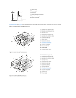
Page 50 highlights
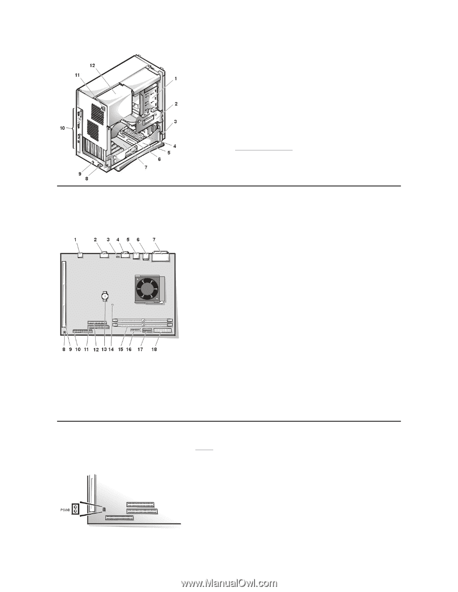
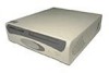
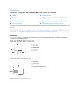
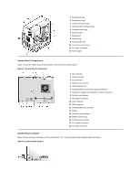
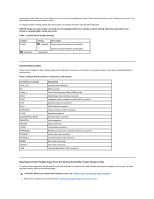
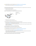
1 External drive bay 2 Internal drive cage 3 Chassis intrusion switch 4 Hard-disk drive interface cable 5 Expansion-card cage 6 System board 7 Riser board 8 Padlock ring 9 Security cable slot 10 I/O ports and connectors 11 AC power receptacle 12 Power supply System Board Components Figure 7 shows the system board and the location of all its sockets and connectors. Figure 7. System Board Components 1 NIC connector 2 Video connector 3 Fan connector 4 Serial port 2 connector 5 USB connectors (2) 6 Keyboard (lower) and mouse (upper) connectors 7 Parallel port (upper) and serial port 1 (lower) connectors 8 System board jumpers 9 Riser board connector 10 IDE1 connector 11 IDE2 connector 12 Diskette/tape-drive connector 13 Battery 14 Auxiliary power indicator 15 DIMM connectors (2) 16 Control panel connector 17 3.3-V power connector 18 DC power connector System Board Jumpers Figure 8 shows the layout of jumpers on the system board. Table 1 lists the system board jumpers and their settings. Figure 8. System Board Jumpers
-
 1
1 -
2
-
3
-
4
-
5
-
6
-
7
-
8
-
9
-
10
-
11
-
12
-
13
-
14
-
15
-
16
-
17
-
18
-
19
-
20
-
21
-
22
-
23
-
24
-
25
-
26
-
27
-
28
-
29
-
30
-
31
-
32
-
33
-
34
-
35
-
36
-
37
-
38
-
39
-
40
-
41
-
42
-
43
-
44
-
 45
45 -
 46
46 -
 47
47 -
 48
48 -
 49
49 -
 50
50 -
 51
51 -
 52
52 -
 53
53 -
 54
54 -
 55
55 -
56
-
57
-
58
-
59
-
60
-
61
-
62
-
63
-
64
-
65
-
66
-
67
-
68
-
69
-
70
-
71
-
72
-
73
-
74
-
75
-
76
-
77
-
78
-
79
-
80
-
81
-
82
-
83
-
84
-
85
-
86
-
87
-
88
-
89
-
90
-
91
-
92
-
93
-
94
-
95
-
96
-
97
-
98
-
99
-
100
-
101
-
102
-
103
-
104
-
105
-
106
-
107
 |
 |