Dell OptiPlex GX100 User Guide - Page 77
Microprocessor: Dell™ OptiPlex™ GX100 System User's Guide
 |
View all Dell OptiPlex GX100 manuals
Add to My Manuals
Save this manual to your list of manuals |
Page 77 highlights
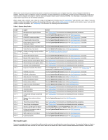
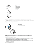
Back to Contents Page Microprocessor: Dell™ OptiPlex™ GX100 System User's Guide Upgrading the Microprocessor Upgrading the Microprocessor NOTE: Dell recommends that only a technically knowledgeable person perform this procedure. CAUTION: Before you remove the computer cover, see "Safety First-For You and Your Computer." To replace the microprocessor, perform the following procedure. CAUTION: To avoid the possibility of electric shock, turn off the computer and any peripherals, disconnect them from their electrical outlets, and then wait at least 15 seconds before you remove the computer cover. Also, before you upgrade the microprocessor, see the other precautions in "Safety First-For You and Your Computer." 1. Remove the computer cover according to the instructions in "Removing and Replacing the Computer Cover." 2. If you are working in the small-form-factor chassis or low-profile chassis, it may be helpful to remove the power supply. If you are working in the mini tower chassis, it may be helpful to lay the computer on its side, and then rotate the power supply out of the way. For instructions, see "Rotating the Power Supply Away From the System Board (Mini Tower Chassis Only)." 3. If you are working in the mini tower chassis, remove the airflow shroud. Pull up on the release tabs (see Figure 1) while you lift and rotate the bottom of the shroud up and away from the microprocessor/heat sink assembly. Remove the shroud tabs from the chassis hooks, and lift the shroud out of the chassis. Figure 1. Airflow Shroud, Heat Sink Assembly, and Microprocessor 1 Shroud tabs (2) 2 Chassis hooks (2) 3 Release tabs (2) CAUTION: The microprocessor and heat sink assembly can get extremely hot. Be sure the assembly has had sufficient time to cool before you touch it. 4. If you are working in the small-form-factor chassis or low-profile chassis, disconnect the cooling fan power cable from the system board connector. Then remove the two thumbscrews securing the cooling fan to the heat sink. Lift the cooling fan from the microprocessor/heat sink assembly. Figure 2. Cooling Fan, Heat Sink Assembly, and Microprocessor
-
 1
1 -
2
-
3
-
4
-
5
-
6
-
7
-
8
-
9
-
10
-
11
-
12
-
13
-
14
-
15
-
16
-
17
-
18
-
19
-
20
-
21
-
22
-
23
-
24
-
25
-
26
-
27
-
28
-
29
-
30
-
31
-
32
-
33
-
34
-
35
-
36
-
37
-
38
-
39
-
40
-
41
-
42
-
43
-
44
-
45
-
46
-
47
-
48
-
49
-
50
-
51
-
52
-
53
-
54
-
55
-
56
-
57
-
58
-
59
-
60
-
61
-
62
-
63
-
64
-
65
-
66
-
67
-
68
-
69
-
70
-
71
-
 72
72 -
 73
73 -
 74
74 -
 75
75 -
 76
76 -
 77
77 -
 78
78 -
 79
79 -
 80
80 -
 81
81 -
 82
82 -
83
-
84
-
85
-
86
-
87
-
88
-
89
-
90
-
91
-
92
-
93
-
94
-
95
-
96
-
97
-
98
-
99
-
100
-
101
-
102
-
103
-
104
-
105
-
106
-
107
 |
 |