Dell PowerEdge 6800 Installation and Troubleshooting Guide (.htm) - Page 12
assembly to the tower front panel.
 |
View all Dell PowerEdge 6800 manuals
Add to My Manuals
Save this manual to your list of manuals |
Page 12 highlights
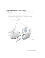
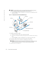
www.dell.com | support.dell.com 4 Remove the control panel assembly: a Orient the system so that the front panel hangs over the edge of the table as shown in Figure 1-5. b Disconnect the interface cables from the control panel assembly. c Using a #2 Phillips screwdriver, remove the three screws that secure the control panel assembly to the tower front panel. d Slide the control panel assembly back away from the front panel and remove the assembly from the chassis. Figure 1-5. Removing and Installing the Control Panel Assembly and Front Panel control panel assembly interface cables (2) screws (3) front panel flat-head T-10 Torx screws (4) 12 Tower-to-Rack Conversion Guide pan-head T-15 Torx screws (21)
-
 1
1 -
2
-
3
-
4
-
5
-
6
-
 7
7 -
 8
8 -
 9
9 -
 10
10 -
 11
11 -
 12
12 -
 13
13 -
 14
14 -
 15
15 -
 16
16
 |
 |
12
Tower-to-Rack Conversion Guide
www.dell.com | support.dell.com
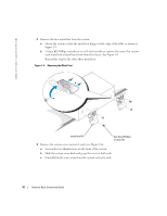
4
Remove the control panel assembly:
a
Orient the system so that the front panel hangs over the edge of the table as shown in
Figure 1-5.
b
Disconnect the interface cables from the control panel assembly.
c
Using a #2 Phillips screwdriver, remove the three screws that secure the control panel
assembly to the tower front panel.
d
Slide the control panel assembly back away from the front panel and remove the assembly
from the chassis.
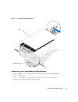
Figure 1-5.
Removing and Installing the Control Panel Assembly and Front Panel
control panel assembly
screws (3)
pan-head T-15 Torx
screws (21)
front panel
interface cables (2)
flat-head T-10 Torx screws (4)