Dell PowerEdge 6800 Installation and Troubleshooting Guide (.htm) - Page 14
Using a #2 Phillips screwdriver, install the two screws that secure the LCD board to
 |
View all Dell PowerEdge 6800 manuals
Add to My Manuals
Save this manual to your list of manuals |
Page 14 highlights
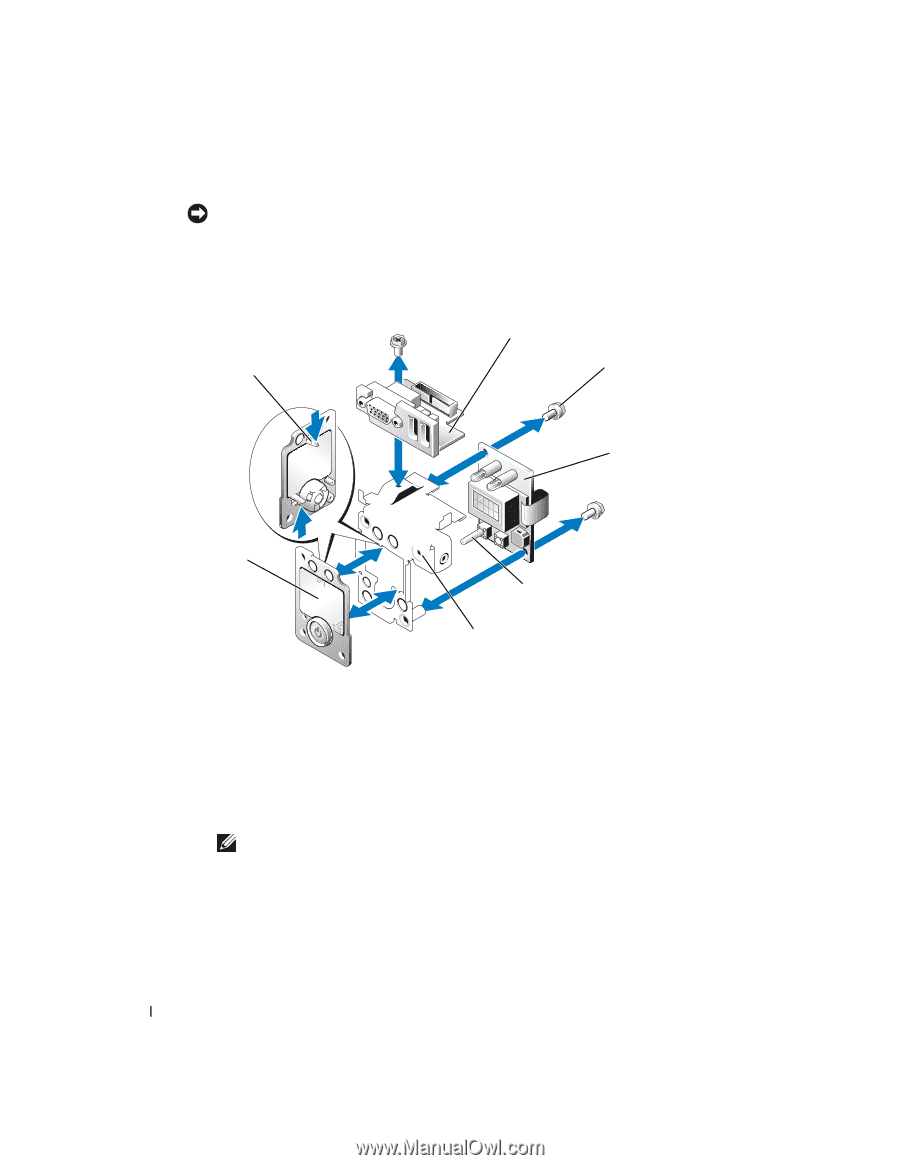
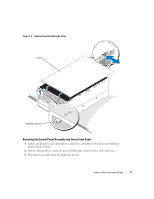
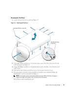
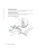
www.dell.com | support.dell.com NOTICE: The system identification switch is very fragile. When aligning the LCD board on the rack carrier, be careful not to damage the system identification switch. See Figure 1-6. h Using a #2 Phillips screwdriver, install the two screws that secure the LCD board to the replacement bracket. Figure 1-6. Replacing the Control Panel Assembly Metal Bracket tabs (3) I/O board screws (3) LCD board front plate system identification switch control panel bracket 3 Install the control panel assembly: a Connect the interface cables to the control panel assembly. b Position the control panel assembly with the panel cutouts on the back of the rack front panel. c Using a #2 Phillips screwdriver, install the three screws (that came with your kit). 4 Connect any cables to the devices previously removed from the media bay. 5 Reinstall the media bay devices, hard drives, and filler plates into the system. NOTE: Ensure that the hard drives, any optical drives, and devices are reinstalled into the same positions that they were removed from. The devices should be labeled appropriately. 6 Install the top cover. See Figure 1-4. 14 Tower-to-Rack Conversion Guide
-
 1
1 -
2
-
3
-
4
-
5
-
6
-
7
-
8
-
 9
9 -
 10
10 -
 11
11 -
 12
12 -
 13
13 -
 14
14 -
 15
15 -
 16
16
 |
 |