Dell PowerEdge SC1430 Hardware Owner's Manual - Page 73
Microprocessor, Removing the Processor - download
 |
View all Dell PowerEdge SC1430 manuals
Add to My Manuals
Save this manual to your list of manuals |
Page 73 highlights
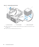
on the system board (see Figure 6-2 for the connector location). If your expansion card has two interface connectors, connect the data cable to the primary controller interface connector. See "Hard Drives" on page 48 for information about connecting hard drives. Microprocessor You can upgrade the system processor(s) to take advantage of future options in speed and functionality, or add a second processor. Each processor and its associated internal cache memory are contained in a land grid array (LGA) package that is installed in a ZIF socket on the system board. Removing the Processor CAUTION: Only trained service technicians are authorized to remove the system cover and access any of the components inside the system. See your Product Information Guide for complete information about safety precautions, working inside the computer, and protecting against electrostatic discharge. 1 Prior to upgrading your system, download the latest system BIOS version on support.dell.com. 2 Turn off the system, including any attached peripherals, and disconnect the system from the electrical outlet. 3 Open the system. See "Opening the System" on page 43. NOTICE: When you remove the heat sink, the possibility exists that the processor might adhere to the heat sink and be removed from the socket. It is recommended that you remove the heat sink while the processor is still warm. NOTICE: Never remove the heat sink from a processor unless you intend to remove the processor. The heat sink is necessary to maintain proper thermal conditions. 4 Rotate the hard-drive carrier out of the system. See "Rotating the Hard-Drive Carrier Out of the System" on page 44. 5 Rotate the processor access door to its open position. See Figure 3-21. NOTE: To loosen the four captive screws on the sides of the heat-sink assembly, you need a Phillips screwdriver with at least a 6-inch blade. 6 Loosen but do not remove the four screws on the sides of the heat-sink assembly. Leave the screws in place to retain the springs under the screws. 7 Wait 30 seconds for the heat sink to loosen from the processor. 8 Lift to remove the heat-sink assembly from the system. 9 If the heat sink has not separated from the processor, carefully rotate the heat sink in a clockwise, then counterclockwise, direction until it releases from the processor. Do not pry the heat sink off of the processor. 10 Lift the heat sink off of the processor and set the heat sink aside. Installing System Components 73
-
 1
1 -
2
-
3
-
4
-
5
-
6
-
7
-
8
-
9
-
10
-
11
-
12
-
13
-
14
-
15
-
16
-
17
-
18
-
19
-
20
-
21
-
22
-
23
-
24
-
25
-
26
-
27
-
28
-
29
-
30
-
31
-
32
-
33
-
34
-
35
-
36
-
37
-
38
-
39
-
40
-
41
-
42
-
43
-
44
-
45
-
46
-
47
-
48
-
49
-
50
-
51
-
52
-
53
-
54
-
55
-
56
-
57
-
58
-
59
-
60
-
61
-
62
-
63
-
64
-
65
-
66
-
67
-
 68
68 -
 69
69 -
 70
70 -
 71
71 -
 72
72 -
 73
73 -
 74
74 -
 75
75 -
 76
76 -
 77
77 -
 78
78 -
79
-
80
-
81
-
82
-
83
-
84
-
85
-
86
-
87
-
88
-
89
-
90
-
91
-
92
-
93
-
94
-
95
-
96
-
97
-
98
-
99
-
100
-
101
-
102
-
103
-
104
-
105
-
106
-
107
-
108
-
109
-
110
-
111
-
112
-
113
-
114
-
115
-
116
-
117
-
118
-
119
-
120
-
121
-
122
-
123
-
124
-
125
-
126
-
127
-
128
-
129
-
130
-
131
-
132
-
133
-
134
-
135
-
136
-
137
-
138
-
139
-
140
-
141
-
142
-
143
-
144
-
145
-
146
-
147
-
148
-
149
-
150
-
151
-
152
-
153
-
154
-
155
-
156
-
157
-
158
-
159
-
160
 |
 |
