Dell PowerEdge SC1430 Hardware Owner's Manual - Page 77
General Memory Module Installation Guidelines, Non-Optimal Memory Configurations
 |
View all Dell PowerEdge SC1430 manuals
Add to My Manuals
Save this manual to your list of manuals |
Page 77 highlights
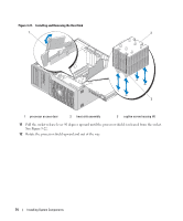
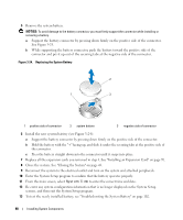
General Memory Module Installation Guidelines To ensure optimal performance of your system, observe the following guidelines when configuring your system memory. • Use only qualified FBDs. FBDs can be either single-ranked or dual-ranked. FBDs marked with a 1R are single-ranked and modules marked with a 2R are dual-ranked. • A minimum of two identical FBDs must be installed. • DIMM sockets must be populated by lowest number first. • FBDs must be installed in pairs of matched memory size, speed, and technology. For best system performance, all FBDs should be identical memory size, speed, and technology. Non-Optimal Memory Configurations System performance can be affected if your memory configuration does not conform to the preceding installation guidelines. Your system may issue an error message during startup stating that your memory configuration is non-optimal. Installing Memory Modules CAUTION: Only trained service technicians are authorized to remove the system cover and access any of the components inside the system. See your Product Information Guide for complete information about safety precautions, working inside the computer, and protecting against electrostatic discharge. 1 Turn off the system, including any attached peripherals, and disconnect the system from the electrical outlet. 2 Open the system. See "Opening the System" on page 43. 3 Rotate the hard-drive carrier out of the system. See "Rotating the Hard-Drive Carrier Out of the System" on page 44. 4 Locate the memory module sockets on the system board. See Figure 6-2. CAUTION: The DIMMs are hot to the touch for some time after the system has been powered down. Allow time for the DIMMs to cool before handling them. Handle the DIMMs by the card edges and avoid touching the DIMM components. 5 Press the ejectors on the memory module socket down and out, as shown in Figure 3-23, to allow the memory module to be inserted into the socket. Installing System Components 77
-
 1
1 -
2
-
3
-
4
-
5
-
6
-
7
-
8
-
9
-
10
-
11
-
12
-
13
-
14
-
15
-
16
-
17
-
18
-
19
-
20
-
21
-
22
-
23
-
24
-
25
-
26
-
27
-
28
-
29
-
30
-
31
-
32
-
33
-
34
-
35
-
36
-
37
-
38
-
39
-
40
-
41
-
42
-
43
-
44
-
45
-
46
-
47
-
48
-
49
-
50
-
51
-
52
-
53
-
54
-
55
-
56
-
57
-
58
-
59
-
60
-
61
-
62
-
63
-
64
-
65
-
66
-
67
-
68
-
69
-
70
-
71
-
 72
72 -
 73
73 -
 74
74 -
 75
75 -
 76
76 -
 77
77 -
 78
78 -
 79
79 -
 80
80 -
 81
81 -
 82
82 -
83
-
84
-
85
-
86
-
87
-
88
-
89
-
90
-
91
-
92
-
93
-
94
-
95
-
96
-
97
-
98
-
99
-
100
-
101
-
102
-
103
-
104
-
105
-
106
-
107
-
108
-
109
-
110
-
111
-
112
-
113
-
114
-
115
-
116
-
117
-
118
-
119
-
120
-
121
-
122
-
123
-
124
-
125
-
126
-
127
-
128
-
129
-
130
-
131
-
132
-
133
-
134
-
135
-
136
-
137
-
138
-
139
-
140
-
141
-
142
-
143
-
144
-
145
-
146
-
147
-
148
-
149
-
150
-
151
-
152
-
153
-
154
-
155
-
156
-
157
-
158
-
159
-
160
 |
 |