Dell Precision 400 Service Manual (.pdf) - Page 76
System Board, When you reinstall the system board, before you slide the system board back
 |
View all Dell Precision 400 manuals
Add to My Manuals
Save this manual to your list of manuals |
Page 76 highlights
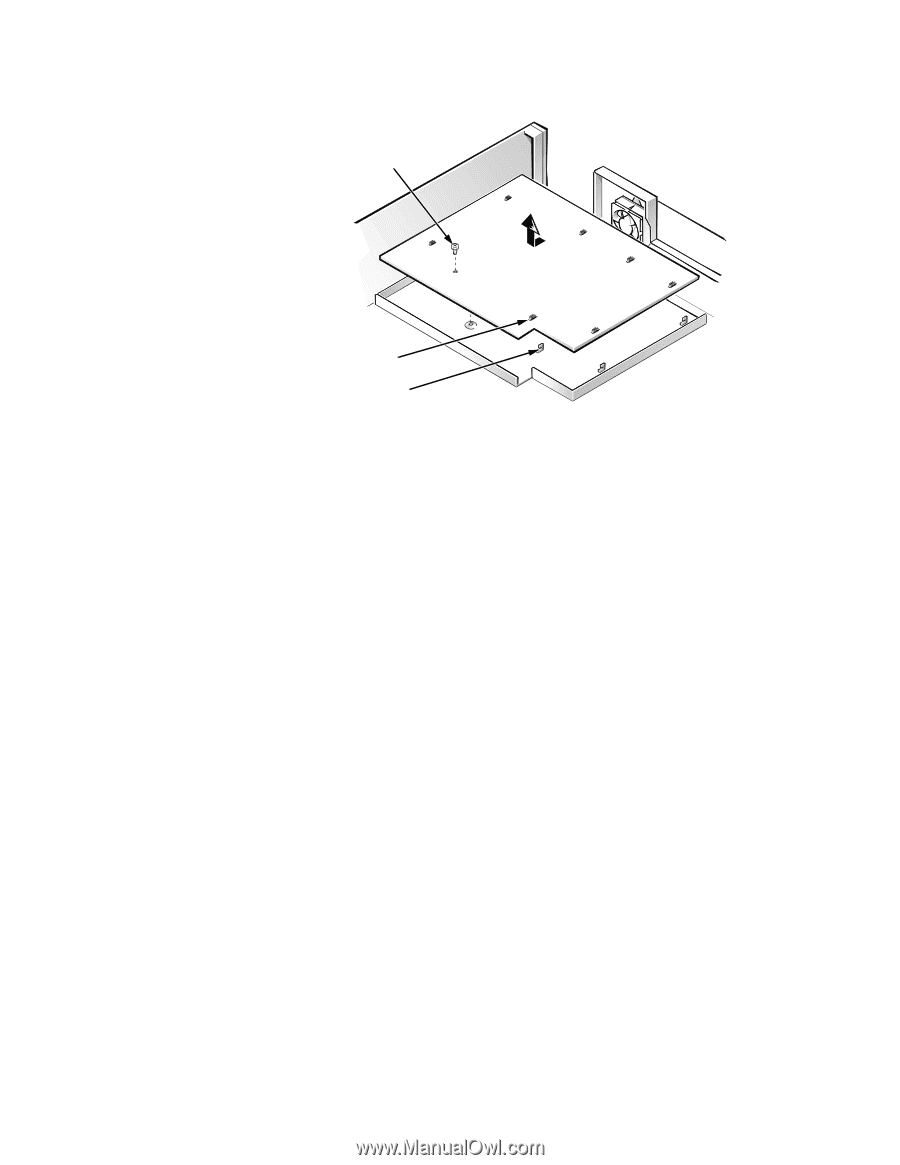
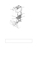
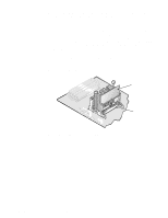
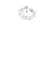
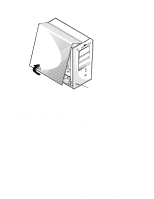
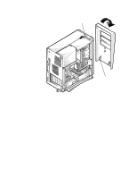
System Board screw slots (7) tabs (7) Figure 4-25. System Board Removal To remove the system board, follow these steps: 1. Rotate the power supply out of the way (see Figure 4-14). 2. Disconnect all cables from their connectors at the back of the computer. 3. Remove the expansion-card cage. 4. Remove the microprocessor fan. 5. Disconnect all cables from the system board. 6. Remove the hard-disk drive power cable(s). Slide any drives in the 5.25-inch bays toward the front of the computer, but leave them cabled. 7. Remove the screw that secures the system board to the bottom of the computer. 8. Slide the system board toward the front of the chassis until it stops. 9. Carefully lift the system board out of the chassis (be sure to lift evenly and not twist the system board). If you are replacing a system board, remove the DIMMs, the primary processor SEC cartridge/heat sink assembly, and the terminator card or secondary processor assembly, and install them on the replacement board. When you reinstall the system board, before you slide the system board back to lock it into position, push down near each slot to engage the grounding clip onto its corresponding tab. Push evenly on both sides of the system board as you slide it into position (do not twist the system board). 4-24 Dell WorkStation 400 Systems Service Manual
-
 1
1 -
2
-
3
-
4
-
5
-
6
-
7
-
8
-
9
-
10
-
11
-
12
-
13
-
14
-
15
-
16
-
17
-
18
-
19
-
20
-
21
-
22
-
23
-
24
-
25
-
26
-
27
-
28
-
29
-
30
-
31
-
32
-
33
-
34
-
35
-
36
-
37
-
38
-
39
-
40
-
41
-
42
-
43
-
44
-
45
-
46
-
47
-
48
-
49
-
50
-
51
-
52
-
53
-
54
-
55
-
56
-
57
-
58
-
59
-
60
-
61
-
62
-
63
-
64
-
65
-
66
-
67
-
68
-
69
-
70
-
 71
71 -
 72
72 -
 73
73 -
 74
74 -
 75
75 -
 76
76 -
 77
77 -
 78
78 -
 79
79 -
 80
80 -
 81
81 -
82
-
83
-
84
-
85
-
86
-
87
-
88
-
89
-
90
-
91
-
92
-
93
-
94
-
95
-
96
-
97
-
98
-
99
-
100
-
101
-
102
-
103
-
104
-
105
-
106
-
107
-
108
-
109
-
110
-
111
-
112
-
113
-
114
-
115
-
116
-
117
-
118
 |
 |