Dell S3048-ON VxFlex Network Deployment Guide using EMC Networking 25GbE switc - Page 23
VMware virtual network design - console
 |
View all Dell S3048-ON manuals
Add to My Manuals
Save this manual to your list of manuals |
Page 23 highlights
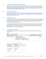
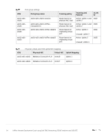
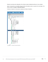
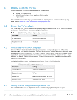
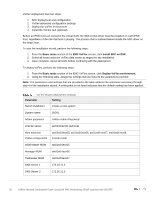
5 5.1 5.2 5.3 VMware virtual network design Tables are provided in this section that outline the virtual network design used in this deployment. Specific steps to create the distributed switches, VMkernels, and setting NIC teaming policies are not covered in this document. See vSphere Networking Guide for vSphere 6.5, ESXi 6.5, and vCenter Server 6.5 for details on configuring ESXi and the virtual network environment. ESXi management The default VMkernel, vmk0 is used for management and is migrated from the default standard switch to the VDS created in this section. See How to migrate service console / VMkernel port from standard switches to VMware vSphere Distributed Switch. Load balancing In the deployment, two different load balancing algorithms are used. VxFlex data networks (Data1 and Data2) use Route based on Originating Virtual Port. Each port group is assigned a single interface as active while the other interface is unused. This creates a traditional storage topology where each host has two separate networks both logically and physically. The remaining port groups use Route based on Physical NIC Load. Both uplinks are set as active, and I/O is automatically balanced across both interfaces. The Virtual Distributed Switch (VDS) tests the associated uplinks every 30 seconds, and if their load exceeds 75 percent of usage, the port ID of the virtual machine with the highest I/O is moved to a different uplink. Configuration details The following tables contain the pre- and post-installation configuration details for the VDS used for the VxFlex cluster. Virtual switch details VDS switch name Function Physical NIC port count MTU atx01-w01-vds01 • ESXI_VMOTION_IP 2 • HOST_AND_SVM_MGMT_IP • Node_DATA1_IP and SVM_DATA1_IP • Node_DATA2_IP and SVM_DATA2_IP 9000 Port group configuration settings Parameter Settings Failover Detection Link status only Notify switches Enabled Failback Yes 23 VxFlex Network Deployment Guide using Dell EMC Networking 25GbE switches and OS10EE
-
 1
1 -
2
-
3
-
4
-
5
-
6
-
7
-
8
-
9
-
10
-
11
-
12
-
13
-
14
-
15
-
16
-
17
-
 18
18 -
 19
19 -
 20
20 -
 21
21 -
 22
22 -
 23
23 -
 24
24 -
 25
25 -
 26
26 -
 27
27 -
 28
28 -
29
-
30
-
31
-
32
-
33
-
34
-
35
-
36
-
37
-
38
-
39
-
40
-
41
-
42
-
43
-
44
 |
 |
