Dell Studio XPS 13 Owner's Manual (PDF) - Page 56
Replacing the Display Assembly - hinge
 |
UPC - 883685979287
View all Dell Studio XPS 13 manuals
Add to My Manuals
Save this manual to your list of manuals |
Page 56 highlights
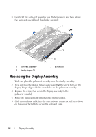
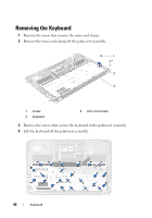
8 Gently lift the palm-rest assembly to a 90-degree angle and then release the palm-rest assembly off the display assembly. 1 2 3 1 palm-rest assembly 3 display hinges (2) 2 screws (4) Replacing the Display Assembly 1 Slide and place the palm-rest assembly over the display assembly. 2 Press down on the display hinges and ensure that the screw holes on the display hinges align with the screw holes on the palm-rest assembly. 3 Replace the screws that secure the display assembly to the palm-rest assembly. 4 Route the mini-card cables through the routing guides. 5 Slide the touchpad cable into the system-board connector and press down on the connector latch to secure the keyboard cable. 56 Display Assembly
-
 1
1 -
2
-
3
-
4
-
5
-
6
-
7
-
8
-
9
-
10
-
11
-
12
-
13
-
14
-
15
-
16
-
17
-
18
-
19
-
20
-
21
-
22
-
23
-
24
-
25
-
26
-
27
-
28
-
29
-
30
-
31
-
32
-
33
-
34
-
35
-
36
-
37
-
38
-
39
-
40
-
41
-
42
-
43
-
44
-
45
-
46
-
47
-
48
-
49
-
50
-
 51
51 -
 52
52 -
 53
53 -
 54
54 -
 55
55 -
 56
56 -
 57
57 -
 58
58 -
 59
59 -
 60
60 -
 61
61 -
62
-
63
-
64
-
65
-
66
-
67
-
68
-
69
-
70
-
71
-
72
-
73
-
74
 |
 |

56
Display Assembly
8
Gently lift the palm-rest assembly to a 90-degree angle and then release
the palm-rest assembly off the display assembly.
Replacing the Display Assembly
1
Slide and place the palm-rest assembly over the display assembly.
2
Press down on the display hinges and ensure that the screw holes on the
display hinges align with the screw holes on the palm-rest assembly.
3
Replace the screws that secure the display assembly to the
palm-rest assembly.
4
Route the mini-card cables through the routing guides.
5
Slide the touchpad cable into the system-board connector and press down
on the connector latch to secure the keyboard cable.
1
palm-rest assembly
2
screws (4)
3
display hinges (2)
3
1
2