Dell U2723QE Monitor Simplified Service Manual - Page 10
bracket, then remove the Mylar tape from the hooks
 |
View all Dell U2723QE manuals
Add to My Manuals
Save this manual to your list of manuals |
Page 10 highlights
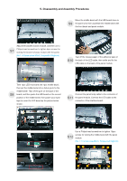
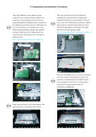
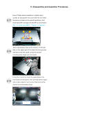
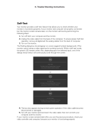
5. Disassembly and Assembly Procedures Take away the bracket chassis module and then put S14 the bracket chassis module on a protective cushion. Remove the power board board and interface S17 board from the bracket chassis module carefully, and then disconnect all of the cables. Release the panel lamp cables from the hooks of the S15 bracket, then remove the Mylar tape from the hooks of the bracket. Use a Philips-head screwdriver to remove 8pcs screws for interface board and power board. S16 (No.1 screw size=M4x8, Torque=7±1kgfxcm; No.2~8 screw size=M3x7.5, Torque=7±1kgfxcm) 6 7 2 8 3 1 54
-
 1
1 -
2
-
3
-
4
-
 5
5 -
 6
6 -
 7
7 -
 8
8 -
 9
9 -
 10
10 -
 11
11 -
 12
12 -
 13
13 -
 14
14 -
 15
15 -
16
-
17
-
18
-
19
-
20
-
21
-
22
-
23
-
24
-
25
-
26
 |
 |

5. Disassembly and Assembly Procedures
Use a Philips-head screwdriver to remove
screws for interface board and power board.
8pcs
(No.1 screw size=M4x8, Torque=7
±1
kgfxcm;
No.2~8 screw size=M3x7.5, Torque=7
±1
kgfxcm)
S16
Remove the power board board and interface
board
from the
disconnect all of the cables.
bracket chassis module carefully,
and then
Release the panel lamp cables from the hooks of the
bracket, then remove the Mylar tape from the hooks
of the bracket.
S15
S17
Take away the bracket chassis module and then put
the bracket chassis module on a protective cushion.
S14
1
3
4
2
6
8
7
5