Dell U2723QE Monitor Simplified Service Manual - Page 9
with the panel
 |
View all Dell U2723QE manuals
Add to My Manuals
Save this manual to your list of manuals |
Page 9 highlights
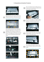
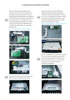
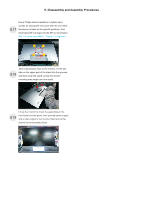
5. Disassembly and Assembly Procedures Use a Philips-head screwdriver to remove 18(13+5)pcs screws for unlocking the middle bezel S8 with the panel module. (No.1~13 screw size=M3x5, Torque=5±0.5kgfxcm; No.13~18 screw size=M3x4.5, Torque=5±0.5kgfxcm) 5 7 8 11 2 10 1 9 64 13 3 12 15 17 14 18 16 Disconnect the two panel lamp cables from the S9 connectors of the panel. Disconnect the LED cable from the connector of the interface board. Lift up the middle bezel, and then put it on a cushion S11 foam for later disassembling. Tear off the tape on the middle bezel for releasing the S12 LED cable, and then tear off the mylar tape to release the LED board for the hooks of the middle bezel. Use a Philips-head screwdriver to remove 4pcs screws for unlocking the bracket chassis module S10 with the panel. (No.1~4 Screw size= M3x5, Torque=5±0.5kgfxcm) 1 3 Move up the bracket, then push the earing-lock and S13 disconnect the LVDS cable away from the connectors of the panel module. 4 2
-
 1
1 -
2
-
3
-
 4
4 -
 5
5 -
 6
6 -
 7
7 -
 8
8 -
 9
9 -
 10
10 -
 11
11 -
 12
12 -
 13
13 -
 14
14 -
15
-
16
-
17
-
18
-
19
-
20
-
21
-
22
-
23
-
24
-
25
-
26
 |
 |
