Dell U2723QE Monitor Simplified Service Manual - Page 12
No.1~4 Screw size= M3x5, Torque=5, kgfxcm, No.1~13 screw size=M3x5, Torque=5
 |
View all Dell U2723QE manuals
Add to My Manuals
Save this manual to your list of manuals |
Page 12 highlights
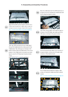
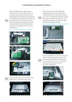
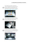
5. Disassembly and Assembly Procedures Move the middle bezel with the LED board close to S9 the panel unit, then assemble the middle bezel with the front bezel and panel module. Adjust the bracket chassis module, and then use a Philips-head screwdriver to tighten 4pcs screws for S7 locking the bracket chassis module with the panel. (No.1~4 Screw size= M3x5, Torque=5±0.5kgfxcm) 1 1 Tear off the release paper of the adhesive tape on S10 the back of the LED cable, then settle and fix the LED cable on the back of the panel module. 1 4 Take 1pcs LED key board and 1pcs middle bezel, then put the middle bezel into a fixture jip to fix the middle bezel. Tear off the gum on the back of the S8 board, and then paste the LED board on the correct position of the middle bezel, then paste 1pcs mylar tape to cover the LED board as the picture below shown. Connect the panel lamp cable to the connector of S11 the panel module. Connect the LED cable to the connector of the interface board. Use a Philips-head screwdriver to tighten 13pcs screws for locking the middle bezel with the panel S12 module. (No.1~13 screw size=M3x5, Torque=5±0.5kgfxcm) 5 7 2 1 6 4 3 8 9 13 12 11 10
-
 1
1 -
2
-
3
-
4
-
5
-
6
-
 7
7 -
 8
8 -
 9
9 -
 10
10 -
 11
11 -
 12
12 -
 13
13 -
 14
14 -
 15
15 -
 16
16 -
 17
17 -
18
-
19
-
20
-
21
-
22
-
23
-
24
-
25
-
26
 |
 |
