Dell U2723QE Monitor Simplified Service Manual - Page 11
Assembly Procedures
 |
View all Dell U2723QE manuals
Add to My Manuals
Save this manual to your list of manuals |
Page 11 highlights
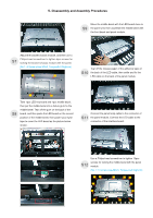
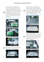
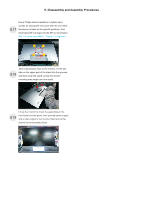
5. Disassembly and Assembly Procedures 5.1 Assembly Procedures: Place a bracket chassis base on a protective S1 cushion, then stick 4pcs Silicon sheets on the positions as the picture below shown. Take a black mylar to insert the hooks of the bracket to cover the power board, then tear off the gum S4 paper of the panel lamp cable and locate the cable into the hook of the bracket.. Take a power board and put the power board into S2 the bracket chassis, settle the cable to the correct position. Panel preparation: Take out 1pcs panel module from the carton, remove the protective film by tearing off the tapes, then examine the panel surface according S5 to inspection criteria of the panel. Turn over the panel module to place the screen faced down for later assembling. Take a interface board, connect 1pcs LVDS cable and 1pcs panel lamp cable to the connectors of the interface board, then connect the cable of the power board with interface board. Turn over the interface S3 board and locate it to the bracket. Use a Philips-head screwdriver to tighten 7pcs screws for locking the interface board and power board. (No.1 screw size=M4x8, Torque=7.5±0.5kgfxcm; No.2~7 screw size=M4x8, Torque=7.5±0.5kgfxcm) 6 7 5 3 1 2 4 Move the bracket chassis module close to the panel module, then connect the LVDS cable to the S6 connector of the panel module, then turn over the bracket chassis and put it on the back of the bracket chassis module.
-
 1
1 -
2
-
3
-
4
-
5
-
 6
6 -
 7
7 -
 8
8 -
 9
9 -
 10
10 -
 11
11 -
 12
12 -
 13
13 -
 14
14 -
 15
15 -
 16
16 -
17
-
18
-
19
-
20
-
21
-
22
-
23
-
24
-
25
-
26
 |
 |
