Dell Vostro 5502 Service Manual
Dell Vostro 5502 Manual
 |
View all Dell Vostro 5502 manuals
Add to My Manuals
Save this manual to your list of manuals |
Dell Vostro 5502 manual content summary:
- Dell Vostro 5502 | Service Manual - Page 1
Vostro 5502 Service Manual Regulatory Model: P102F Regulatory Type: P102F002 October 2020 Rev. A01 - Dell Vostro 5502 | Service Manual - Page 2
of data and tells you how to avoid the problem. WARNING: A WARNING indicates a potential for property damage, personal injury, or death. © 2020 Dell Inc. or its subsidiaries. All rights reserved. Dell, EMC, and other trademarks are trademarks of Dell Inc. or its subsidiaries. Other trademarks may be - Dell Vostro 5502 | Service Manual - Page 3
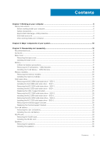
instructions...6 Before working inside your computer...6 Safety precautions...7 Electrostatic discharge-ESD protection...7 ESD field service solid-state drive - SSD-2 29 Removing the thermal support bracket...30 Replacing the thermal support bracket...31 Coin-cell battery...32 Removing the coin- - Dell Vostro 5502 | Service Manual - Page 4
Heat sink...37 Removing the heat sink - UMA...37 Installing the heat sink - UMA...38 System fan...39 Removing the system fan...39 Installing the system fan...40 I/O board...42 Removing the I/O board...42 Installing the I/O board...43 System board...44 Removing the system board...44 Installing the - Dell Vostro 5502 | Service Manual - Page 5
enabled 78 Updating the Dell BIOS in Linux and Ubuntu environments 78 Flashing the BIOS from the F12 One-Time boot menu 78 System and setup password...83 Assigning a system setup password...84 Deleting or changing an existing system setup password 84 Chapter 6: Troubleshooting...85 Built-in self - Dell Vostro 5502 | Service Manual - Page 6
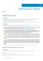
only perform troubleshooting and simple repairs as authorized in your product documentation, or as directed by the online or telephone service and support team. Damage due to servicing that is not authorized by Dell is not covered by your warranty. Read and follow the safety instructions that came - Dell Vostro 5502 | Service Manual - Page 7
instructions. field service kit when working inside any notebook to 15 seconds should discharge residual power in the system board. Remove the battery from notebooks such as intermittent problems or a shortened product Dell products, the sensitivity to static damage is now higher than in previous Dell - Dell Vostro 5502 | Service Manual - Page 8
more difficult type of damage to recognize and troubleshoot is the intermittent (also called latent or " and the hardware is known as bonding. Use only Field Service kits with a wrist strap, mat, and bonding wire. Never parts to be returned to Dell, it is critical to place these parts in anti- - Dell Vostro 5502 | Service Manual - Page 9
grounding wrist strap and protective anti-static mat at all times when servicing Dell products. In addition, it is critical that technicians keep sensitive parts separate from all insulator parts while performing service and that they use anti-static bags for transporting sensitive components. After - Dell Vostro 5502 | Service Manual - Page 10
SSD 8. Speaker 9. System board 10. Touchpad 11. Palm-rest and keyboard assembly 12. Display assembly 13. Power button with fingerprint reader 14. Coin-cell battery 15. I/O board 16. System fan 17. WLAN card 10 Major components of your system - Dell Vostro 5502 | Service Manual - Page 11
18. M.2 2280 SSD NOTE: Dell provides a list of components and their part numbers for the original system configuration purchased. These parts are available according to warranty coverages purchased by the customer. Contact your Dell sales representative for purchase options. Major components of - Dell Vostro 5502 | Service Manual - Page 12
3 Disassembly and reassembly Topics: • Recommended tools • Screw list • Base cover • Battery • Memory modules • Solid-state drive • Coin-cell battery • WLAN card • Speakers • Heat sink • System fan • I/O board • System board • DC-in port • Power button with fingerprint reader (optional) • Touchpad - Dell Vostro 5502 | Service Manual - Page 13
continued) Component Screw type Quantity 3-Cell Battery 4-Cell Battery Solid-state drive (slot 1) Solid-state drive (slot 2) Solid-state drive thermal support bracket WLAN Heat sink System fan Hinge screws M2x3 4 M2x3 5 M2x3 1 M2x3 1 M1.6x2 2 M2x3 1 M2x5.35 - captive 4 M2x2 2 M2 - Dell Vostro 5502 | Service Manual - Page 14
Base cover Removing the base cover Prerequisites Follow the procedure in before working inside your computer. About this task The figure indicates the location of the base cover and provides a visual representation of the removal procedure. 14 Disassembly and reassembly - Dell Vostro 5502 | Service Manual - Page 15
installation procedure. About this task The figure indicates the location of the base cover and provides a visual representation of the installation procedure. Disassembly and reassembly 15 - Dell Vostro 5502 | Service Manual - Page 16
16 Disassembly and reassembly - Dell Vostro 5502 | Service Manual - Page 17
Steps 1. Place the base cover on the palm-rest and keyboard assembly, and snap the base cover into place. 2. Tighten the two captive screws (M2x8) that secure the base cover to the palm-rest and keyboard assembly. 3. Replace the seven screws (M2x4) that secure the base cover to the palm-rest and - Dell Vostro 5502 | Service Manual - Page 18
to pry on or against the battery. ● Ensure any screws during the servicing of this product are not lost or misplaced, to prevent accidental puncture or damage dell.com or authorized Dell partners and resellers. Removing the 3-cell battery - UMA/discrete Prerequisites NOTE: Vostro 5501 also supports - Dell Vostro 5502 | Service Manual - Page 19
Prerequisites If you are replacing a component, remove the existing component before performing the installation procedure. About this task NOTE: Vostro 5501 also supports 4-cell battery. The figure indicates the location of the 3-cell battery and provides a visual representation of the installation - Dell Vostro 5502 | Service Manual - Page 20
Memory modules Removing the memory modules Prerequisites 1. Follow the procedure in before working inside your computer. 2. Remove the base cover. About this task The figure indicates the location of the memory module and provides a visual representation of the removal procedure. Steps 1. Lift the - Dell Vostro 5502 | Service Manual - Page 21
Installing the memory modules Prerequisites If you are replacing a component, remove the existing component before performing the installation procedure. About this task The figure indicates the location of the memory module and provides a visual representation of the installation procedure. Steps - Dell Vostro 5502 | Service Manual - Page 22
the base cover. 3. Disconnect the battery. NOTE: Depending on the configuration ordered, your computer may support a 2230 solid-state drive or a 2280 solid-state drive in M.2 slot one. NOTE: M.2 slot two supports one PCIe Gen3 x4 NVMe or SATA solid-state drive (M.2 2230 or M.2 2280) or one Intel - Dell Vostro 5502 | Service Manual - Page 23
the base cover. 3. Disconnect the battery. NOTE: Depending on the configuration ordered, your computer may support a 2230 solid-state drive or a 2280 solid-state drive in M.2 slot one. NOTE: M.2 slot two supports one PCIe Gen3 x4 NVMe or SATA solid-state drive (M.2 2230 or M.2 2280) or one Intel - Dell Vostro 5502 | Service Manual - Page 24
component before performing the installation procedure. NOTE: Depending on the configuration ordered, your computer may support a 2230 solid-state drive or a 2280 solid-state drive in M.2 slot one. NOTE: M.2 slot two supports one PCIe Gen3 x4 NVMe or SATA solid-state drive (M.2 2230 or M.2 2280) or - Dell Vostro 5502 | Service Manual - Page 25
steps 1. Connect the battery. 2. Install the base cover. 3. Follow the procedure in after working inside your computer. Replacing the SSD-1 support bracket Prerequisites 1. Follow the procedure in before working inside your computer. 2. Remove the base cover. 3. Remove the battery. 4. Remove the - Dell Vostro 5502 | Service Manual - Page 26
bracket slot. 2. Depending on the type of solid-state drive (M.2 2230/ M.2 2280), align and insert the SSD support bracket into the support bracket slot. 3. Install the solid-state drive. Removing the M.2 2280 solid-state drive - SSD-2 Prerequisites 1. Follow the procedure in before working inside - Dell Vostro 5502 | Service Manual - Page 27
component before performing the installation procedure. NOTE: Depending on the configuration ordered, your computer may support a 2230 solid-state drive or a 2280 solid-state drive in M.2 slot one. NOTE: M.2 slot two supports one PCIe Gen3 x4 NVMe or SATA solid-state drive (M.2 2230 or M.2 2280) or - Dell Vostro 5502 | Service Manual - Page 28
the base cover. 3. Disconnect the battery. NOTE: Depending on the configuration ordered, your computer may support a 2230 solid-state drive or a 2280 solid-state drive in M.2 slot one. NOTE: M.2 slot two supports one PCIe Gen3 x4 NVMe or SATA solid-state drive (M.2 2230 or M.2 2280) or one Intel - Dell Vostro 5502 | Service Manual - Page 29
component before performing the installation procedure. NOTE: Depending on the configuration ordered, your computer may support a 2230 solid-state drive or a 2280 solid-state drive in M.2 slot one. NOTE: M.2 slot two supports one PCIe Gen3 x4 NVMe or SATA solid-state drive (M.2 2230 or M.2 2280) or - Dell Vostro 5502 | Service Manual - Page 30
steps 1. Connect the battery. 2. Install the base cover. 3. Follow the procedure in after working inside your computer. Removing the thermal support bracket Prerequisites 1. Follow the procedure in before working inside your computer. 2. Remove the base cover. 3. Remove the battery. 4. Remove the - Dell Vostro 5502 | Service Manual - Page 31
Steps 1. Remove the two screws (M1.6x2) that secures the thermal support bracket to palm-rest and keyboard assembly. 2. Lift the thermal support bracket. Replacing the thermal support bracket Prerequisites If you are replacing a component, remove the existing component before performing the - Dell Vostro 5502 | Service Manual - Page 32
bracket. 3. Depending on the type of solid-state drive (M.2 2230/ M.2 2280), align and insert the SSD support bracket into the support bracket slot. 4. Install the solid-state drive. Next steps 1. Install the SSD-2. 2. Connect the battery. 3. Install the base cover. 4. Follow the procedure in - Dell Vostro 5502 | Service Manual - Page 33
Installing the coin-cell battery Prerequisites If you are replacing a component, remove the existing component before performing the installation procedure. About this task The figure indicates the location of the coin-cell battery and provides a visual representation of the installation procedure. - Dell Vostro 5502 | Service Manual - Page 34
Steps 1. Remove the screw (M2x3) that secures the WLAN card bracket to the WLAN card. 2. Remove the WLAN card bracket from the WLAN card. 3. Disconnect the antenna cables from the WLAN card. 4. Slide and remove the WLAN card from the WLAN card slot. Installing the WLAN card Prerequisites If you are - Dell Vostro 5502 | Service Manual - Page 35
Steps 1. Align the notch on the WLAN card with the tab on the WLAN card slot and insert the WLAN card at an angle into the WLAN card slot. 2. Connect the antenna cables to the WLAN card. 3. Align and place the WLAN card bracket on the WLAN card. 4. Replace the screw (M2x3) to secure the WLAN card - Dell Vostro 5502 | Service Manual - Page 36
About this task The figure indicates the location of the speakers and provides a visual representation of the removal procedure. Steps 1. Locate the speakers on your computer. 2. Disconnect the speaker cable from the connector on the system board. 3. Peel the adhesive tape that secures the speaker - Dell Vostro 5502 | Service Manual - Page 37
posts and rubber grommets, place the speakers in the slots on the palm-rest and keyboard assembly. 2. Route the speaker cable through the routing guides on the palm-rest and keyboard assembly. 3. Connect the speaker cable to the system board. Next steps 1. Install the battery. 2. Install the base - Dell Vostro 5502 | Service Manual - Page 38
1. Follow the procedure in before working inside your computer. 2. Remove the base cover. 3. Remove the battery. 4. Remove the fan. About this task The figure indicates the location of the heat sink and provides a visual representation of the removal procedure. Steps 1. In sequential order (as - Dell Vostro 5502 | Service Manual - Page 39
Steps 1. Place the heat sink on the system board and align the screw holes on the heat sink with the screw holes on the system board. 2. In sequential order (as indicated on the heat sink), tighten the four captive screws (M2x3) that secure the heat sink to the system board. Next steps 1. Install - Dell Vostro 5502 | Service Manual - Page 40
Steps 1. Flip the mylar cover. 2. Unplug the I/O cable from the connector on the system board. 3. Peel the adhesive tape to unroute the I/O cable. 4. Disconnect the system fan cable from the system board. 5. Remove the two (M2x2) screws that secure the system fan to the palm-rest and keyboard - Dell Vostro 5502 | Service Manual - Page 41
Steps 1. Slide and place the system fan on the palm-rest and keyboard assembly. 2. Align the screw holes on the system fan with the screw holes on the palm-rest and keyboard assembly. 3. Replace the two (M2x2) screws to secure the system fan to the palm-rest and keyboard assembly. 4. Connect the - Dell Vostro 5502 | Service Manual - Page 42
I/O board Removing the I/O board Prerequisites 1. Follow the procedure in before working inside your computer. 2. Remove the base cover. 3. Remove the battery. 4. Remove the WLAN card. 5. Remove the SSD-1 (M.2 2280 or M.2 2230). 6. Remove the coin cell. About this task The figure indicates the - Dell Vostro 5502 | Service Manual - Page 43
6. Open the latch, and disconnect the fingerprint reader cable from the I/O board. 7. Disconnect the coin-cell battery cable from the I/O board. 8. Remove the four screws (M2x2) that secure the I/O board to the palm-rest and keyboard assembly. 9. Lift the I/O board off the palm-rest and keyboard - Dell Vostro 5502 | Service Manual - Page 44
8. Lower the left hinge, and replace the three screws (M2.5x3.5). 9. Place the mylar cover back. Next steps 1. Install the system fan. 2. Install the battery. 3. Install the base cover. 4. Follow the procedure in after working inside your computer. System board Removing the system board - Dell Vostro 5502 | Service Manual - Page 45
Disassembly and reassembly 45 - Dell Vostro 5502 | Service Manual - Page 46
Steps 1. Remove three screws (M2.5x3.5), and lift the left-display hinge. 2. Peel the adhesive tape off the I/O-board cable to system board. 3. Open the latch, and disconnect the I/O-board cable from the system board. 4. Disconnect the system fan cable from the system board. 5. Open the latch, and - Dell Vostro 5502 | Service Manual - Page 47
Disassembly and reassembly 47 - Dell Vostro 5502 | Service Manual - Page 48
Steps 1. Slide the ports on the system board into the slots on the palm-rest and keyboard assembly and align the screw holes on the system board with the screw holes on the palm-rest and keyboard assembly. 2. Replace the two screws (M2x2) that secure the system board to the palm-rest and keyboard - Dell Vostro 5502 | Service Manual - Page 49
2. Install the memory module. 3. Install the heat sink. 4. Install the system fan. 5. Install the WLAN card. 6. Install the SSD-1 (M.2 2280 solid-state drive or M.2 2230 solid-state drive). 7. Install the SSD-2 (M.2 2280 solid-state drive or M.2 2230 solid-state drive). 8. Install the battery. 9. - Dell Vostro 5502 | Service Manual - Page 50
indicates the location of the DC-in port and provides a visual representation of the installation procedure. Steps 1. Locate the DC-in port on your laptop. 2. Replace the single (M2x3) screw, and connect the DC-in cable to the system board. 3. Adhere the adhesive tape and the transparent sticker - Dell Vostro 5502 | Service Manual - Page 51
5. Replace the three (M2.5x3.5) screws and fix the metal hinge to cover the display connector. Next steps 1. Install the battery. 2. Install the base cover. 3. Follow the procedure in after working inside your computer. Power button with fingerprint reader (optional) Removing the power button and - Dell Vostro 5502 | Service Manual - Page 52
Installing the power button with optional finger reader Prerequisites If you are replacing a component, remove the existing component before performing the installation procedure. About this task The figure indicates the location of the power button with fingerprint reader and provides a visual - Dell Vostro 5502 | Service Manual - Page 53
Touchpad Removing the touchpad Prerequisites 1. Follow the procedure in before working inside your computer. 2. Remove the base cover. 3. Remove the battery. 4. Remove the speakers. About this task The figure indicates the location of the touchpad and provides a visual representation of the removal - Dell Vostro 5502 | Service Manual - Page 54
4. Open the latch, and disconnect the touchpad cable from the system board. 5. Remove the adhesive tape from the touchpad bracket. 6. Remove the two (M2x2) screws that secure the touchpad bracket to the palm-rest and keyboard assembly. 7. Lift the touchpad, along with the cable, off the palm-rest - Dell Vostro 5502 | Service Manual - Page 55
5. Align and place the touchpad bracket into the slot on the palm-rest and keyboard assembly. 6. Replace the three (M1.6x2) screws that secure the touchpad bracket to the palm-rest and keyboard assembly. 7. Route the audio cable, and replace the adhesive tape. Next steps 1. Install the speakers. 2. - Dell Vostro 5502 | Service Manual - Page 56
56 Disassembly and reassembly - Dell Vostro 5502 | Service Manual - Page 57
Disassembly and reassembly 57 - Dell Vostro 5502 | Service Manual - Page 58
Steps 1. Locate the display cable and display hinges on your computer. 2. Peel the tape that secures the display cable to the system board. 3. Open the latch, and disconnect the display cable from the system board. 4. Remove the three screws (M2.5x3.5) that secure the left-display hinge to the - Dell Vostro 5502 | Service Manual - Page 59
Disassembly and reassembly 59 - Dell Vostro 5502 | Service Manual - Page 60
Steps 1. Place the display assembly on a clean and flat surface. 2. Align and place the palm-rest and keyboard assembly on the display assembly. 3. Using the alignment posts, close the display hinges. 4. Replace the three screws (M2.5x3.5) that secure the left-display hinge to the system board. 5. - Dell Vostro 5502 | Service Manual - Page 61
. Remove the heat sink. 11. Remove the speakers. 12. Remove the display assembly. 13. Remove the I/O board. 14. Remove the power button with fingerprint reader. 15. Remove the DC-in port. 16. Remove the touchpad. 17. Remove the system board. NOTE: The system board can be removed along with the heat - Dell Vostro 5502 | Service Manual - Page 62
2280 solid-state drive or M.2 2230 solid-state drive). 12. Install the memory module. 13. Install the coin-cell battery. 14. Install the WLAN card. 15. Install the battery. 16. Install the base cover. 17. Follow the procedure in after working inside your computer. 62 Disassembly and reassembly - Dell Vostro 5502 | Service Manual - Page 63
drivers Steps 1. Turn on the notebook. 2. Go to Dell.com/support. 3. Click Product Support, enter the Service Tag of your notebook, and then click Submit. NOTE: If you do not have the Service Tag, use the auto detect feature or manually browse for your notebook model. 4. Click Drivers and Downloads - Dell Vostro 5502 | Service Manual - Page 64
Topics: • Boot menu • Navigation keys • Boot Sequence • BIOS setup • Updating the BIOS in Windows • System and setup password Boot menu Press when the Dell logo appears to initiate a one-time boot menu with a list of the valid boot devices for the system. Diagnostics and BIOS Setup options are - Dell Vostro 5502 | Service Manual - Page 65
or hard drive). During the Power-on Self-Test (POST), when the Dell logo appears, you can: ● Access System Setup by pressing F2 key screen. BIOS setup NOTE: Depending on the laptop and its installed devices, the items listed in version ○ Service Tag ○ Asset Tag ○ Manufacture Date ○ Ownership - Dell Vostro 5502 | Service Manual - Page 66
Table 2. Overview Option Boot configuration Table 3. Boot configuration Option Boot Sequence 66 System setup Description ○ Signed Firmware Update ● Battery ○ Primary ○ Battery Level ○ Battery State ○ Health ○ AC Adapter ● Processor Information ○ Processor Type ○ Maximum Clock Speed ○ Minimum - Dell Vostro 5502 | Service Manual - Page 67
device options Option Date/Time Camera Audio USB Configuration Description ● Onboard NIC (IPV4) ● Onboard NIC (IPV6) NOTE: Legacy Boot mode is not supported on this platform. Secure Boot helps ensure your system boots using only validated boot software. Enable Secure Boot-By default, this option is - Dell Vostro 5502 | Service Manual - Page 68
Table 4. Integrated device options (continued) Option Disable USB4 PCIE Tunneling Description ● Enable USB Boot Support ● Enable External USB Port By default, all the options are enabled. By default the Disable USB4 PCIE Tunneling is disabled. Storage Table 5. Storage options Option - Dell Vostro 5502 | Service Manual - Page 69
Table 6. Display options (continued) Option Description By default, all the option is disabled. Connection options Table 7. Connection Option Integrated NIC Wireless Device Enable Enable UEFI Network Stack Description Integrated NIC controls the onboard LAN controller. It allows pre-OS and early - Dell Vostro 5502 | Service Manual - Page 70
this option is disabled. NOTE: The user can: ● Set Battery Threshold Min = 15, Max = 100 ● Prevent AC power between certain times of the day using Peak Cool ● Quiet ● Ultra Performance USB Wake Support Wake on Dell USB-C Dock Allows you to connect a Dell USB-C Dock to wake the system from standby - Dell Vostro 5502 | Service Manual - Page 71
. Absolute This field allows you to Enable, Disable, or Permanently Disable the BIOS module interface of the optional Absolute Persistence Module service from Absolute® Software. The options are: ● Enabled-This option is enabled by default. ● Disabled ● Permanently Disable Absolute UEFI Boot Path - Dell Vostro 5502 | Service Manual - Page 72
disabled, the BIOS setup can be entered and items that are viewed in Locked mode. Master Password Lockout Allows you to disable master password support. Enable Master Password Lockout - By default, this option is disabled. NOTE: The Hard Disk password has to be cleared before the settings can be - Dell Vostro 5502 | Service Manual - Page 73
then all the automatic boot flow for SupportAssist OS Recovery tool is disabled. BIOSConnect Dell Auto OS Recovery Threshold Allows you to recover cloud service operating system if the main operating system and/or local service operating system fails to boot with the number of failures equal to or - Dell Vostro 5502 | Service Manual - Page 74
when an AC adapter is plugged in the system. The options are: ● 5 seconds ● 10 seconds - This option is enabled by default. ● 15 seconds ● 30 seconds ● 1 minute ● 5 minutes ● 15 minutes ● Never NOTE: If Never is selected, the backlight stays on always when the system has AC adapter plugged in. This - Dell Vostro 5502 | Service Manual - Page 75
Table 13. Keyboard (continued) Option Description ● 10 seconds - This option is enabled by default. ● 15 seconds ● 30 seconds ● 1 minute ● 5 minutes ● 15 minutes ● Never NOTE: If Never is selected, the backlight stays on always when the system is running on battery power. Pre-boot behavior - Dell Vostro 5502 | Service Manual - Page 76
Virtualization support Table 15. Virtualization Support Option Description Intel Virtualization Technology This option specifies option is enabled. Performance Table 16. Performance Option Multi Core Support Intel SpeedStep C-States Control Enable Adaptive C-states for Discrete Graphics Intel - Dell Vostro 5502 | Service Manual - Page 77
you replace the system board or if an update is available. For laptops, ensure that your computer battery is fully charged and connected to a 2. Go to Dell.com/support. ● Enter the Service Tag or Express Service Code and click Submit. ● Click Detect Product and follow the instructions on screen. 3. - Dell Vostro 5502 | Service Manual - Page 78
to install the updated BIOS settings on your computer. Follow the instructions on the screen. Updating BIOS on systems with BitLocker enabled CAUTION: have to be bootable). ● BIOS executable file that you downloaded from the Dell Support website and copied to the root of the USB drive. ● AC power - Dell Vostro 5502 | Service Manual - Page 79
The Flash BIOS opens. 4. Click Flash from file. System setup 79 - Dell Vostro 5502 | Service Manual - Page 80
5. Select external USB device. 6. Once the file is selected, double-click the flash target file and click Submit. 80 System setup - Dell Vostro 5502 | Service Manual - Page 81
7. Click Update BIOS for the system to reboot and flash the BIOS. System setup 81 - Dell Vostro 5502 | Service Manual - Page 82
8. Click Confirm Update BIOS. 82 System setup - Dell Vostro 5502 | Service Manual - Page 83
Once complete, the system reboots and the BIOS update process is completed. System and setup password Table 18. System and setup password Password type System password Setup password Description Password that you must enter to log on to your system. Password that you must enter to access and make - Dell Vostro 5502 | Service Manual - Page 84
Assigning a system setup password Prerequisites You can assign a new System or Admin Password only when the status is in Not Set. About this task To enter the system setup, press F2 immediately after a power-on or reboot. Steps 1. In the System BIOS or System Setup screen, select Security and press - Dell Vostro 5502 | Service Manual - Page 85
system board embedded controller (EC) failures. M-BIST must be manually initiated before POST and can also run on a dead system 19. Functions Purpose Trigger Indicator of fault Repair instruction M-Bist Evaluates the health condition of the system problem with the system board. Troubleshooting 85 - Dell Vostro 5502 | Service Manual - Page 86
by performing an LCD Power Rail test. If there is no power going to the LCD, the battery status LED flashes a [2,8] LED error code. 86 Troubleshooting - Dell Vostro 5502 | Service Manual - Page 87
BIST outcome Off Solid amber M-BIST No fault detected with system board. Indicates a problem with the system board. SupportAssist diagnostics About this task The SupportAssist diagnostics (previously known It allows you to: ● Run tests automatically or in an interactive mode Troubleshooting 87 - Dell Vostro 5502 | Service Manual - Page 88
completed successfully ● View error messages that indicate if problems were encountered during the test NOTE: Some tests computer. 2. As the computer boots, press the F12 key as the Dell logo appears. 3. On the boot menu screen, select the Diagnostics 1, 7 - 1, 8 - 1, 9 - 88 Troubleshooting - Dell Vostro 5502 | Service Manual - Page 89
3,8 3,9 Problem description CPU troubleshoot and fix your computer when it fails to boot into their primary operating system due to software or hardware failures. For more information about the Dell SupportAssist OS Recovery, see Dell SupportAssist OS Recovery User's Guide at www.dell.com/support - Dell Vostro 5502 | Service Manual - Page 90
BIOS Update Utility appears. Follow the instructions on the screen to complete the BIOS update. Backup media and recovery options It is recommended to create a recovery drive to troubleshoot and fix problems that may occur with Windows. Dell proposes multiple options for recovering Windows operating - Dell Vostro 5502 | Service Manual - Page 91
it from the port and pull the plug backward [1, 2]. 2. Lift at an angle when disconnecting the ethernet cable from the RJ-45 port (Ethernet port) [3,4]. Troubleshooting 91 - Dell Vostro 5502 | Service Manual - Page 92
. Availability varies by country and product, and some services may not be available in your area. To contact Dell for sales, technical support, or customer service issues: Steps 1. Go to Dell.com/support. 2. Select your support category. 3. Verify your country or region in the Choose a Country
-
 1
1 -
 2
2 -
 3
3 -
 4
4 -
 5
5 -
 6
6 -
 7
7 -
8
-
9
-
10
-
11
-
12
-
13
-
14
-
15
-
16
-
17
-
18
-
19
-
20
-
21
-
22
-
23
-
24
-
25
-
26
-
27
-
28
-
29
-
30
-
31
-
32
-
33
-
34
-
35
-
36
-
37
-
38
-
39
-
40
-
41
-
42
-
43
-
44
-
45
-
46
-
47
-
48
-
49
-
50
-
51
-
52
-
53
-
54
-
55
-
56
-
57
-
58
-
59
-
60
-
61
-
62
-
63
-
64
-
65
-
66
-
67
-
68
-
69
-
70
-
71
-
72
-
73
-
74
-
75
-
76
-
77
-
78
-
79
-
80
-
81
-
82
-
83
-
84
-
85
-
86
-
87
-
88
-
89
-
90
-
91
-
92
 |
 |

Vostro 5502
Service Manual
Regulatory Model: P102F
Regulatory Type: P102F002
October 2020
Rev. A01