Dell W-7024 Controller Installation Guide - Page 11
Uplink Ports
 |
View all Dell W-7024 manuals
Add to My Manuals
Save this manual to your list of manuals |
Page 11 highlights
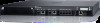
l LINK/ACT- Placed on the left side of the port, this LED displays the link status and activity of the port. l STATUS- Placed on the right side of the port, this LED displays the status of the port. The information displayed by this LED changes based on the LCD mode. The LED behavior corresponding to each LCD mode is listed in Table 5. Table 5: 10/100/1000BASE-T Port LEDs LED Function LCD Mode Indicator Status LINK/ACT Link status Link status Green (Solid) Link established Green (Blinking) Port is transmitting or receiving data Off No link STATUS Port status Administrative Green (Solid) Port enabled Off Port administratively disabled Duplex Green (Solid) Full-duplex Off Half-duplex PoE Green (Solid) PoE enabled Green (Blinking) Power enabled, but power denied due to unavailability Off PoE not enabled Speed Green (Solid) 1000 Mbps Off 10/100 Mbps Uplink Ports The W-7024 controller is equipped with two 10GBase-X (SFP+) uplink ports (24 and 25). These ports are intended for use with SFP/SFP+. See Figure 4. Figure 4: 10GBase-X Ports, LCD Panel, and LEDs Uplink Port LEDs Each 10GBASE-X port is equipped with two LEDs that allow basic monitoring of status, activity, and configuration of the port. The behavior of the STATUS LED can be changed using the LCD. l LINK/ACT- Placed on the top left of the port, this LED displays the link status and activity of the port. 11 | W-7024 Controller Dell Networking W-7024 Controller | Installation Guide
-
 1
1 -
2
-
3
-
4
-
5
-
 6
6 -
 7
7 -
 8
8 -
 9
9 -
 10
10 -
 11
11 -
 12
12 -
 13
13 -
 14
14 -
 15
15 -
 16
16 -
17
-
18
-
19
-
20
-
21
-
22
-
23
-
24
-
25
-
26
-
27
-
28
-
29
-
30
-
31
-
32
 |
 |
