Dell W-7024 Controller Installation Guide - Page 13
Management Port, Power, Status, and Peered LEDs, Table 8
 |
View all Dell W-7024 manuals
Add to My Manuals
Save this manual to your list of manuals |
Page 13 highlights
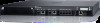
Table 8: Supported SFP/SFP+ Modules SFP/SFP+ Description SFP-SX SFP, 1000BASE-SX, LC Connector; 850nm pluggable GbE optic; up to 300 meters over multi-mode fiber (Type OM2). SFP-LX SFP, 1000BASE-LX, LC Connector; 310nm pluggable GbE optic; up to 10,000 meters over single-mode fiber. SFP-TX SFP, 1000BASE-T SFP; copper GbE pluggable; RJ45 connector; up to 100 meters over Category-5, 5e, 6 and 6a unshielded twisted pair cable. SFP-EX 1000BASE-ZX SFP; 1310nm pluggable GbE optic; LC connector; up to 40,000 meters over singlemode fiber. SFP-ZX 1000BASE-ZX SFP; 1310nm pluggable GbE optic; LC connector; up to 70,000 meters over singlemode fiber SFP-10G-SR SFP+, 10GBASE-SR, 850nm serial pluggable SFP+ optic, target range 300m over MMF, LC Connector SFP-10G-LR SFP+, 10GBASE-LR, 1310nm serial pluggable SFP+ optic for up to 10km over SMF, LC Connector SFP-10G-LRM SFP+, 10GBASE-LRM, 1310nm serial pluggable SFP+ optic, long-reach multimode, LC Connector SFP-10G-ER SFP+, 10GBASE-ER, 1310nm pluggable 10GE optic; up to 40,000 meters over single-mode fiber, LC connector SFP-10G-ZR SFP+, 10GBASE-ZR, 1310nm pluggable 10GE optic; up to 70,000 meters over single-mode fiber, LC connector Management Port The W-7024 controller is equipped with a 10/100/1000BASE-T Gigabit Management (RJ-45) port on the front (see Figure 4). The management port provides 10/100/1000 Mbps Ethernet access to the controller CLI, SNMP, and Web interface for complete system management and troubleshooting. It can also be used to connect to a separate management network. The management port has a LINK/ACT LED on its left side and SPEED LED on its right side. During operation, these LEDs provide status information as shown in the following table: Table 9: 10/100/1000BASE-T (RJ-45) Management Port LED Function Indicator Status LINK/ACT Link Status Green (Solid) Link established Green (Blinking) Link activity Off No link on port SPEED Interface Speed Green (Solid) 1000Mbps Off 10/100Mbps Power, Status, and Peered LEDs The front panel of the controller also includes Power, Status, and Peered LEDs (see Figure 4), that provide basic monitoring of the overall status of the controller. The following table describes the different behavior of these LEDs: 13 | W-7024 Controller Dell Networking W-7024 Controller | Installation Guide
-
 1
1 -
2
-
3
-
4
-
5
-
6
-
7
-
 8
8 -
 9
9 -
 10
10 -
 11
11 -
 12
12 -
 13
13 -
 14
14 -
 15
15 -
 16
16 -
 17
17 -
 18
18 -
19
-
20
-
21
-
22
-
23
-
24
-
25
-
26
-
27
-
28
-
29
-
30
-
31
-
32
 |
 |
