Dell XPS 13 9310 2-in-1 XPS 13 2-in-1 9310 2n1 Service Manual
Dell XPS 13 9310 2-in-1 Manual
 |
View all Dell XPS 13 9310 2-in-1 manuals
Add to My Manuals
Save this manual to your list of manuals |
Dell XPS 13 9310 2-in-1 manual content summary:
- Dell XPS 13 9310 2-in-1 | XPS 13 2-in-1 9310 2n1 Service Manual - Page 1
XPS 13 2-in-1 (9310 2n1) Service Manual Regulatory Model: P103G Regulatory Type: P103G002 September 2020 Rev. A00 - Dell XPS 13 9310 2-in-1 | XPS 13 2-in-1 9310 2n1 Service Manual - Page 2
of data and tells you how to avoid the problem. WARNING: A WARNING indicates a potential for property damage, personal injury, or death. © 2020 Dell Inc. or its subsidiaries. All rights reserved. Dell, EMC, and other trademarks are trademarks of Dell Inc. or its subsidiaries. Other trademarks may be - Dell XPS 13 9310 2-in-1 | XPS 13 2-in-1 9310 2n1 Service Manual - Page 3
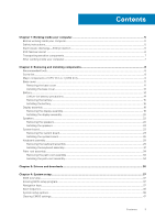
Safety instructions...5 Electrostatic discharge-ESD protection...6 ESD field service kit ...6 Transporting sensitive components...7 After working inside your computer...7 Chapter 2: Removing and installing components 8 Recommended tools...8 Screw list...8 Major components of XPS 13 2-in-1 (9310 2n1 - Dell XPS 13 9310 2-in-1 | XPS 13 2-in-1 9310 2n1 Service Manual - Page 4
Clearing BIOS (System Setup) and System passwords 47 Chapter 5: Troubleshooting...48 Locate the Service Tag or Express Service Code of your Dell computer 48 Recovering the operating system...48 SupportAssist | On-board Diagnostics...48 System diagnostic lights...49 Flashing the BIOS...50 Flashing - Dell XPS 13 9310 2-in-1 | XPS 13 2-in-1 9310 2n1 Service Manual - Page 5
and the contacts. CAUTION: You should only perform troubleshooting and repairs as authorized or directed by the Dell technical assistance team. Damage due to servicing that is not authorized by Dell is not covered by your warranty. See the safety instructions that is shipped with the product or at - Dell XPS 13 9310 2-in-1 | XPS 13 2-in-1 9310 2n1 Service Manual - Page 6
obvious, such as intermittent problems or a shortened product life Dell products, the sensitivity to static damage is now higher than in previous Dell type of damage to recognize and troubleshoot is the intermittent (also called worked on. Once deployed properly, service parts can be removed from the - Dell XPS 13 9310 2-in-1 | XPS 13 2-in-1 9310 2n1 Service Manual - Page 7
for safe transport. ESD protection summary It is recommended that all field service technicians use the traditional wired ESD grounding wrist strap and protective anti-static mat at all times when servicing Dell products. In addition, it is critical that technicians keep sensitive parts separate - Dell XPS 13 9310 2-in-1 | XPS 13 2-in-1 9310 2n1 Service Manual - Page 8
2 Removing and installing components NOTE: The images in this document may differ from your computer depending on the configuration you ordered. Recommended tools The procedures in this document may require the following tools: ● Phillips screwdriver #00 ● Phillips screwdriver #0 ● Torx - Dell XPS 13 9310 2-in-1 | XPS 13 2-in-1 9310 2n1 Service Manual - Page 9
Palm-rest assembly Screw type M1.6x2.5 M1.2x3 M1.2x4 M1.2x1.4 M1.2x1.6 Quantity 4 3 1 captive screw 38 10 Screw image Major components of XPS 13 2-in-1 (9310 2n1) The following image shows the major components of XPS 13 2-in-1 (9310 2n1). Removing and installing components 9 - Dell XPS 13 9310 2-in-1 | XPS 13 2-in-1 9310 2n1 Service Manual - Page 10
1. Base cover 2. Battery 3. System board 4. Left fan 5. Left keyboard bracket 10 Removing and installing components - Dell XPS 13 9310 2-in-1 | XPS 13 2-in-1 9310 2n1 Service Manual - Page 11
6. Palm-rest assembly 7. Left speaker 8. Display assembly 9. Right speaker 10. Keyboard assembly 11. USB Type-C port bracket 12. Right fan NOTE: Dell provides a list of components and their part numbers for the original system configuration purchased. These parts are available according to warranty - Dell XPS 13 9310 2-in-1 | XPS 13 2-in-1 9310 2n1 Service Manual - Page 12
12 Removing and installing components - Dell XPS 13 9310 2-in-1 | XPS 13 2-in-1 9310 2n1 Service Manual - Page 13
. About this task The following images indicate the location of the base cover and provide a visual representation of the installation procedure. Removing and installing components 13 - Dell XPS 13 9310 2-in-1 | XPS 13 2-in-1 9310 2n1 Service Manual - Page 14
Steps 1. Align and secure the back of the base cover on the palm-rest assembly, and then snap the base cover into place. 2. Replace the eight Torx screws (M2x4.5) that secure the base cover to the palm-rest assembly. Next steps 1. Follow the procedure in After working inside your computer. Battery - Dell XPS 13 9310 2-in-1 | XPS 13 2-in-1 9310 2n1 Service Manual - Page 15
to pry on or against the battery. ● Ensure any screws during the servicing of this product are not lost or misplaced, to prevent accidental puncture or damage Dell technical support for assistance. See www.dell.com/contactdell. ● Always purchase genuine batteries from www.dell.com or authorized Dell - Dell XPS 13 9310 2-in-1 | XPS 13 2-in-1 9310 2n1 Service Manual - Page 16
Steps 1. Remove the Torx 5 screw (M1.6x3.4) that secures the battery cable to the system board. 2. Disconnect the battery cable from the interposer board. NOTE: Remove the interposer board immediately after disconnecting the battery cable to avoid misplacing it. Hold the edges of the interposer - Dell XPS 13 9310 2-in-1 | XPS 13 2-in-1 9310 2n1 Service Manual - Page 17
Steps 1. Adhere the magnet and the metal bar to the battery. NOTE: Install the magnet and the metal bar from the faulty battery. 2. Align the screw holes on the battery with the screw holes on the system board and palm-rest assembly. 3. Replace the two screws (M1.2x4) that secure the battery to the - Dell XPS 13 9310 2-in-1 | XPS 13 2-in-1 9310 2n1 Service Manual - Page 18
Display assembly Removing the display assembly Prerequisites 1. Follow the procedure in Before working inside your computer. 2. Remove the base cover. 3. Remove the battery. About this task The following images indicate the location of display assembly and provide a visual representation of the - Dell XPS 13 9310 2-in-1 | XPS 13 2-in-1 9310 2n1 Service Manual - Page 19
tape as a pull tab, disconnect the display cable and camera cable from the system board. 5. Remove the display cable and camera cable from the routing guides on the system board. 6. Remove the four screws (M2.5x3) that secure the display hinges to the palm-rest assembly. 7. Slide the palm-rest - Dell XPS 13 9310 2-in-1 | XPS 13 2-in-1 9310 2n1 Service Manual - Page 20
Installing the display assembly Prerequisites If you are replacing a component, remove the existing component before performing the installation procedure. About this task The following images indicate the location of display assembly and provide a visual representation of the installation procedure - Dell XPS 13 9310 2-in-1 | XPS 13 2-in-1 9310 2n1 Service Manual - Page 21
the four screws (M2.5x3) that secure the display hinges to the palm-rest assembly. 4. Route the display cable and camera cable through the routing guides on the system board. Removing and installing components 21 - Dell XPS 13 9310 2-in-1 | XPS 13 2-in-1 9310 2n1 Service Manual - Page 22
. Steps 1. Disconnect the speaker cable from the system board. 2. Note the routing of the speaker cable and remove the speaker cable from the routing guides on the palm-rest assembly. 3. Using a plastic scribe, pry the speakers off the palm-rest assembly. 22 Removing and installing components - Dell XPS 13 9310 2-in-1 | XPS 13 2-in-1 9310 2n1 Service Manual - Page 23
. NOTE: Ensure that there is no adhesive residue from the faulty speakers that are removed previously. 2. Route the speaker cable through the routing guides on the palm-rest assembly. 3. Connect the speaker cable to the system board. Next steps 1. Install the battery. 2. Install the base cover - Dell XPS 13 9310 2-in-1 | XPS 13 2-in-1 9310 2n1 Service Manual - Page 24
About this task The following image indicates the connectors on your system board. Figure 1. System-board connectors 1. Speaker cable 3. Display cable 5. Keyboard-controller board cable 2. Fingerprint-reader cable 4. Camera cable The following images indicate the location of system board and - Dell XPS 13 9310 2-in-1 | XPS 13 2-in-1 9310 2n1 Service Manual - Page 25
Steps 1. Loosen the captive screw (M1.6x3) that secures the display-cable bracket to the system board. 2. Lift the display-cable bracket off the system board. 3. Peel the tapes that secure the display cable and camera cable to the system board. 4. Using the tape as a pull tab, disconnect the display - Dell XPS 13 9310 2-in-1 | XPS 13 2-in-1 9310 2n1 Service Manual - Page 26
Remove the display cable and camera cable from the routing guides on the system board. 6. Remove the screw (M1. and one captive screw (M1.2x4) that secure the system board to the palm-rest assembly. 13. Lift the system board off the palm-rest assembly. 14. Remove the power-button and fingerprint - Dell XPS 13 9310 2-in-1 | XPS 13 2-in-1 9310 2n1 Service Manual - Page 27
Removing and installing components 27 - Dell XPS 13 9310 2-in-1 | XPS 13 2-in-1 9310 2n1 Service Manual - Page 28
board. NOTE: The M1.6x2 screw has a bigger head than the M1.6x3 screw. 10. Route the display cable and camera cable through the routing guides on the system board. 11. Connect the display cable and camera cable to the system board. 28 Removing and installing components - Dell XPS 13 9310 2-in-1 | XPS 13 2-in-1 9310 2n1 Service Manual - Page 29
12. Adhere the tapes that secure the display cable and camera cable to the system board. 13. Align and place the display-cable bracket on the system board. 14. Tighten the captive screw (M1.6x3) that secures the display-cable bracket to - Dell XPS 13 9310 2-in-1 | XPS 13 2-in-1 9310 2n1 Service Manual - Page 30
30 Removing and installing components - Dell XPS 13 9310 2-in-1 | XPS 13 2-in-1 9310 2n1 Service Manual - Page 31
Steps 1. Peel the fingerprint reader cable from the keyboard. 2. Remove the speaker cable from the routing guides on the left keyboard bracket. 3. Loosen the captive screw that secures the left keyboard bracket to the palm-rest assembly. 4. Using a plastic scribe, pry the - Dell XPS 13 9310 2-in-1 | XPS 13 2-in-1 9310 2n1 Service Manual - Page 32
32 Removing and installing components - Dell XPS 13 9310 2-in-1 | XPS 13 2-in-1 9310 2n1 Service Manual - Page 33
. 8. Tighten the captive screw that secures the left keyboard bracket to the palm-rest assembly. 9. Route the speaker cable through the routing guides on the left keyboard assembly. 10. Adhere the fingerprint reader cable to the keyboard. Next steps 1. Install the system board. 2. Install the - Dell XPS 13 9310 2-in-1 | XPS 13 2-in-1 9310 2n1 Service Manual - Page 34
in the prerequisites. NOTE: Keep the power-button and fingerprint reader bracket if you must replace the palm-rest assembly as the bracket is a separate service part for reuse. NOTE: If the power-button and fingerprint reader bracket is not found on the palm-rest assembly, the bracket should be on - Dell XPS 13 9310 2-in-1 | XPS 13 2-in-1 9310 2n1 Service Manual - Page 35
About this task The following image indicates the palm-rest assembly and provides a visual representation of the installation procedure. Steps Place the palm-rest assembly on a flat surface. NOTE: If you are installing components to a new palm-rest assembly, use the power-button and fingerprint - Dell XPS 13 9310 2-in-1 | XPS 13 2-in-1 9310 2n1 Service Manual - Page 36
3 Drivers and downloads When troubleshooting, downloading or installing drivers it is recommended that you read the Dell Knowledge Based article, Drivers and Downloads FAQ SLN128938. 36 Drivers and downloads - Dell XPS 13 9310 2-in-1 | XPS 13 2-in-1 9310 2n1 Service Manual - Page 37
4 System setup CAUTION: Unless you are an expert computer user, do not change the settings in the BIOS Setup program. Certain changes can make your computer work incorrectly. NOTE: Depending on the computer and its installed devices, the items listed in this section may or may not be displayed. - Dell XPS 13 9310 2-in-1 | XPS 13 2-in-1 9310 2n1 Service Manual - Page 38
: optical drive or hard drive). During the Power-on Self Test (POST), when the Dell logo appears, you can: ● Access System Setup by pressing F2 key ● Bring up the L2 Cache Processor ID Displays the BIOS version number. Displays the Service Tag of the computer. Displays the Asset Tag of the computer - Dell XPS 13 9310 2-in-1 | XPS 13 2-in-1 9310 2n1 Service Manual - Page 39
Table 3. System setup options-System information menu (continued) Overview Processor L3 Cache Displays the processor L3 Cache size. Current Clock Speed Displays the current processor clock speed. Minimum Clock Speed Displays the minimum processor clock speed. Microcode Version Displays the - Dell XPS 13 9310 2-in-1 | XPS 13 2-in-1 9310 2n1 Service Manual - Page 40
the selected onboard drives. Configures operating mode of the integrated SATA hard drive controller. Default: RAID. SATA is configured to support RAID (Intel Rapid Restore Technology). Drive Information Enable Audio Displays the information of various onboard drives. Enables or disables all - Dell XPS 13 9310 2-in-1 | XPS 13 2-in-1 9310 2n1 Service Manual - Page 41
through UEFI capsule update packages. Enables, disables or permanently disable the BIOS module interface of the optional Absolute Persistence Module service from Absolute Software. Default: Enable Absolute. TPM 2.0 Security On Select whether or not the Trusted Platform Model (TPM) is visible - Dell XPS 13 9310 2-in-1 | XPS 13 2-in-1 9310 2n1 Service Manual - Page 42
(admin) password (sometimes called the "setup" password). Sets, Changes, or deletes the system password. Enables or disables the master password support. Default: OFF. Table 8. System setup options-Secure Boot menu Secure Boot Enable Secure Boot Enables or disables the computer to boos using - Dell XPS 13 9310 2-in-1 | XPS 13 2-in-1 9310 2n1 Service Manual - Page 43
the performance of the CPU or graphics processor. Default: ON. Multi-Core Support Changes the number of CPU cores available to the operating system. The default Default: OFF. Wake on Dell USB-C Dock Enables connecting a Dell USB-C Dock to wake the computer from Standby. Default: ON. System - Dell XPS 13 9310 2-in-1 | XPS 13 2-in-1 9310 2n1 Service Manual - Page 44
specified work period. Advanced Battery Charged maximizes battery health while still supporting heavy use during the work day. Default: OFF. Block Sleep Blocks devices. WLAN Default: ON. Bluetooth Default: ON. Table 13. System setup options-POST Behavior menu POST Behavior Numlock Enable - Dell XPS 13 9310 2-in-1 | XPS 13 2-in-1 9310 2n1 Service Manual - Page 45
Table 13. System setup options-POST Behavior menu (continued) POST Behavior Extend BIOS POST of Life. Default: ON. MAC Address Pass-Through Replaces the external NIC MAC address (in a supported dock or dongle) with the selected MAC address from the computer. Default: System Unique MAC Address. - Dell XPS 13 9310 2-in-1 | XPS 13 2-in-1 9310 2n1 Service Manual - Page 46
system. Once set in BIOS, the Asset Tag cannot be changed. Service Tag Displays the Service Tag of the computer. BIOS Recovery from Hard Drive Enables the computer 17. System setup options-SupportAssist menu SupportAssist Dell Auto operating system Recovery Threshold Controls the automatic - Dell XPS 13 9310 2-in-1 | XPS 13 2-in-1 9310 2n1 Service Manual - Page 47
. Clearing BIOS (System Setup) and System passwords About this task To clear the system or BIOS passwords, contact Dell technical support as described at www.dell.com/contactdell. NOTE: For information on how to reset Windows or application passwords, refer to the documentation accompanying Windows - Dell XPS 13 9310 2-in-1 | XPS 13 2-in-1 9310 2n1 Service Manual - Page 48
Troubleshooting Locate the Service Tag or Express Service Code of your Dell computer Your Dell computer is uniquely identified by a Service Tag or Express Service Code. To view relevant support resources for your Dell computer, we recommend entering the Service Tag or Express Service if problems - Dell XPS 13 9310 2-in-1 | XPS 13 2-in-1 9310 2n1 Service Manual - Page 49
light patterns and the associated issues. Table 19. LED codes Diagnostic light codes 2,1 Problem description Processor failure 2,2 System board: BIOS or ROM (Read-Only Memory) failure Power-rail failure 3,6 System BIOS Flash incomplete 3,7 Management Engine (ME) error Troubleshooting 49 - Dell XPS 13 9310 2-in-1 | XPS 13 2-in-1 9310 2n1 Service Manual - Page 50
dell.com/support. 3. Click Product support, enter the Service Tag of your computer, and then click Submit. NOTE: If you do not have the Service Tag, use the auto-detect feature or manually Double-click the BIOS update file icon and follow the instructions on the screen. Flashing BIOS (USB key) Steps - Dell XPS 13 9310 2-in-1 | XPS 13 2-in-1 9310 2n1 Service Manual - Page 51
after it has been powered off and the battery has been removed. The following procedure provides the instructions on how to conduct flea power release: Steps 1. Turn off your computer. 2. Remove the base Replace the battery. 6. Replace the base cover. 7. Turn on your computer. Troubleshooting 51 - Dell XPS 13 9310 2-in-1 | XPS 13 2-in-1 9310 2n1 Service Manual - Page 52
through videos, manuals and documents. In Windows search, type Contact Support, and press Enter. www.dell.com/support/windows Your Dell computer is uniquely identified by a Service Tag or Express Service Code. To view relevant support resources for your Dell computer, enter the Service Tag or
-
 1
1 -
 2
2 -
 3
3 -
 4
4 -
 5
5 -
 6
6 -
 7
7 -
8
-
9
-
10
-
11
-
12
-
13
-
14
-
15
-
16
-
17
-
18
-
19
-
20
-
21
-
22
-
23
-
24
-
25
-
26
-
27
-
28
-
29
-
30
-
31
-
32
-
33
-
34
-
35
-
36
-
37
-
38
-
39
-
40
-
41
-
42
-
43
-
44
-
45
-
46
-
47
-
48
-
49
-
50
-
51
-
52
 |
 |

XPS 13 2-in-1 (9310 2n1)
Service Manual
Regulatory Model: P103G
Regulatory Type: P103G002
September 2020
Rev. A00