Dell XPS 13 9310 2-in-1 XPS 13 2-in-1 9310 2n1 Service Manual - Page 29
Keyboard assembly, Removing the keyboard assembly
 |
View all Dell XPS 13 9310 2-in-1 manuals
Add to My Manuals
Save this manual to your list of manuals |
Page 29 highlights
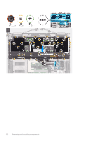
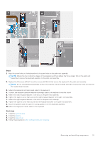
12. Adhere the tapes that secure the display cable and camera cable to the system board. 13. Align and place the display-cable bracket on the system board. 14. Tighten the captive screw (M1.6x3) that secures the display-cable bracket to the system board. Next steps 1. Install the battery. 2. Install the base cover. 3. Follow the procedure in After working inside your computer. Keyboard assembly Removing the keyboard assembly Prerequisites 1. Follow the procedure in Before working inside your computer. 2. Remove the base cover. 3. Remove the battery. 4. Remove the system board. About this task The following images indicate the location of keyboard assembly and provide a visual representation of the removal procedure. Removing and installing components 29
-
 1
1 -
2
-
3
-
4
-
5
-
6
-
7
-
8
-
9
-
10
-
11
-
12
-
13
-
14
-
15
-
16
-
17
-
18
-
19
-
20
-
21
-
22
-
23
-
 24
24 -
 25
25 -
 26
26 -
 27
27 -
 28
28 -
 29
29 -
 30
30 -
 31
31 -
 32
32 -
 33
33 -
 34
34 -
35
-
36
-
37
-
38
-
39
-
40
-
41
-
42
-
43
-
44
-
45
-
46
-
47
-
48
-
49
-
50
-
51
-
52
 |
 |
