Dell XPS 13 9310 2-in-1 XPS 13 2-in-1 9310 2n1 Service Manual - Page 26
Installing the system board, System-board connectors
 |
View all Dell XPS 13 9310 2-in-1 manuals
Add to My Manuals
Save this manual to your list of manuals |
Page 26 highlights
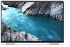
5. Remove the display cable and camera cable from the routing guides on the system board. 6. Remove the screw (M1.6x3) and the screw (M1.6x2) that secures the type-C bracket to the system board. NOTE: The M1.6x2 screw has a bigger head than the M1.6x3 screw. 7. Lift the type-C bracket off the system board. 8. Disconnect the speaker cable from the system board. 9. Open the latch and disconnect the fingerprint-reader cable from the system board. 10. Peel off the fingerprint-reader daughter-board from the system board. 11. Open the latch and disconnect the keyboard-controller board cable from the system board. 12. Remove the four screws (M1.6x2.5), three screws (M1.2x3), and one captive screw (M1.2x4) that secure the system board to the palm-rest assembly. 13. Lift the system board off the palm-rest assembly. 14. Remove the power-button and fingerprint reader bracket from the palm-rest assembly. 15. Place the bracket and the system board on a dry, flat, and clean surface. Installing the system board Prerequisites If you are replacing a component, remove the existing component before performing the installation procedure. About this task The following image indicates the connectors on your system board. Figure 2. System-board connectors 1. Speaker cable 3. Display cable 5. Keyboard-controller board cable 2. Fingerprint-reader cable 4. Camera cable The following images indicate the location of system board and provide a visual representation of the installation procedure. 26 Removing and installing components
-
 1
1 -
2
-
3
-
4
-
5
-
6
-
7
-
8
-
9
-
10
-
11
-
12
-
13
-
14
-
15
-
16
-
17
-
18
-
19
-
20
-
 21
21 -
 22
22 -
 23
23 -
 24
24 -
 25
25 -
 26
26 -
 27
27 -
 28
28 -
 29
29 -
 30
30 -
 31
31 -
32
-
33
-
34
-
35
-
36
-
37
-
38
-
39
-
40
-
41
-
42
-
43
-
44
-
45
-
46
-
47
-
48
-
49
-
50
-
51
-
52
 |
 |
