Dell XPS 13 Plus 9320 XPS 13 Plus 9320 / XPS 9320 Service Manual
Dell XPS 13 Plus 9320 Manual
 |
View all Dell XPS 13 Plus 9320 manuals
Add to My Manuals
Save this manual to your list of manuals |
Dell XPS 13 Plus 9320 manual content summary:
- Dell XPS 13 Plus 9320 | XPS 13 Plus 9320 / XPS 9320 Service Manual - Page 1
XPS 13 Plus 9320 / XPS 9320 Service Manual Regulatory Model: P151G Regulatory Type: P151G001 March 2022 Rev. A00 - Dell XPS 13 Plus 9320 | XPS 13 Plus 9320 / XPS 9320 Service Manual - Page 2
of data and tells you how to avoid the problem. WARNING: A WARNING indicates a potential for property damage, personal injury, or death. © 2022 Dell Inc. or its subsidiaries. All rights reserved. Dell, EMC, and other trademarks are trademarks of Dell Inc. or its subsidiaries. Other trademarks may be - Dell XPS 13 Plus 9320 | XPS 13 Plus 9320 / XPS 9320 Service Manual - Page 3
discharge-ESD protection...6 ESD field service kit ...7 Transporting sensitive components...8 After working inside your computer...8 Chapter 2: Removing and installing components 9 Recommended tools...9 Screw list...9 Major components of XPS 13 Plus 9320...10 Base cover...12 Removing the - Dell XPS 13 Plus 9320 | XPS 13 Plus 9320 / XPS 9320 Service Manual - Page 4
Windows 62 Updating the BIOS from the F12 One-Time boot menu 63 Chapter 5: Troubleshooting...64 Handling swollen Lithium-ion batteries...64 Locate the Service Tag or Express Service Code of your Dell computer 64 System diagnostic lights...65 SupportAssist diagnostics...65 Built-in self-test (BIST - Dell XPS 13 Plus 9320 | XPS 13 Plus 9320 / XPS 9320 Service Manual - Page 5
and the contacts. CAUTION: You should only perform troubleshooting and repairs as authorized or directed by the Dell technical assistance team. Damage due to servicing that is not authorized by Dell is not covered by your warranty. See the safety instructions that is shipped with the product or at - Dell XPS 13 Plus 9320 | XPS 13 Plus 9320 / XPS 9320 Service Manual - Page 6
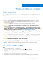
Service Mode or the computer does not support Service for 3 seconds or until the Dell logo appears on the screen. service mode skip this process. Safety precautions The safety precautions chapter details the primary steps to be taken before performing any disassembly instructions problems or - Dell XPS 13 Plus 9320 | XPS 13 Plus 9320 / XPS 9320 Service Manual - Page 7
higher than in previous Dell products. For this The more difficult type of damage to recognize and troubleshoot is the intermittent (also called latent or "walking wounded mat, and the hardware is known as bonding. Use only Field Service kits with a wrist strap, mat, and bonding wire. Never use - Dell XPS 13 Plus 9320 | XPS 13 Plus 9320 / XPS 9320 Service Manual - Page 8
for safe transport. ESD protection summary It is recommended that all field service technicians use the traditional wired ESD grounding wrist strap and protective anti-static mat at all times when servicing Dell products. In addition, it is critical that technicians keep sensitive parts separate - Dell XPS 13 Plus 9320 | XPS 13 Plus 9320 / XPS 9320 Service Manual - Page 9
2 Removing and installing components NOTE: The images in this document may differ from your computer depending on the configuration you ordered. Recommended tools The procedures in this document may require the following tools: ● Phillips screwdriver #0 ● Phillips screwdriver #1 ● Torx #5 (T5) - Dell XPS 13 Plus 9320 | XPS 13 Plus 9320 / XPS 9320 Service Manual - Page 10
fingerprint reader assembly Keyboard Palm-rest and keyboard M1.4x1.2 17 assembly Keyboard Palm-rest and keyboard M1.6x2 7 assembly Major components of XPS 13 Plus 9320 The following image shows the major components of XPS 13 Plus 9320. Screw image 10 Removing and installing components - Dell XPS 13 Plus 9320 | XPS 13 Plus 9320 / XPS 9320 Service Manual - Page 11
-state drive shield 6. Solid-state drive 7. Battery 8. Palm-rest and keyboard assembly 9. Display assembly 10. Power button 11. Battery-connector cover 12. Wireless-module bracket 13. Keyboard 14. Right fan 15. Left fan Removing and installing components 11 - Dell XPS 13 Plus 9320 | XPS 13 Plus 9320 / XPS 9320 Service Manual - Page 12
to warranty coverages purchased by the customer. Contact your Dell sales representative for purchase options. Base cover Removing the base in Before working inside your computer. NOTE: Ensure that your computer is in Service Mode. For more information, see Step 6 in Before working inside your - Dell XPS 13 Plus 9320 | XPS 13 Plus 9320 / XPS 9320 Service Manual - Page 13
thumbs and fingers into the recess at the top edge of the base cover. 3. Use both thumbs to pry the base cover in order to release it from the palm-rest and keyboard assembly. Removing and installing components - Dell XPS 13 Plus 9320 | XPS 13 Plus 9320 / XPS 9320 Service Manual - Page 14
NOTE: Do not pull on or pry the base cover from where the display assembly hinges are, doing so may damage the base cover. 4. Move your hands to both sides of the base cover and lift the base cover off the palm-rest and keyboard assembly. Installing the base cover Prerequisites If you are replacing - Dell XPS 13 Plus 9320 | XPS 13 Plus 9320 / XPS 9320 Service Manual - Page 15
Steps 1. Place and snap the base cover into place on the palm-rest and keyboard assembly. NOTE: Align the screw holes on the base cover with the screw holes on the palm-rest and keyboard assembly before applying slight pressure to the base cover. 2. Replace the six screws (M2x3, Torx 5) that secure - Dell XPS 13 Plus 9320 | XPS 13 Plus 9320 / XPS 9320 Service Manual - Page 16
gets stuck inside your computer as a result of swelling, do not try to release it as puncturing, bending, or crushing a lithium-ion battery can be dangerous. In such an instance, contact Dell technical support for assistance. See www.dell.com/contactdell. ● Always purchase genuine batteries from www - Dell XPS 13 Plus 9320 | XPS 13 Plus 9320 / XPS 9320 Service Manual - Page 17
secure the battery to the palm-rest and keyboard assembly. 5. Use the pull tab to lift the battery slightly from its top edge. This action releases the battery from the two hooks that are located near the bottom edge of the palm-rest and keyboard assembly. CAUTION: Do not lift the - Dell XPS 13 Plus 9320 | XPS 13 Plus 9320 / XPS 9320 Service Manual - Page 18
Installing the battery Prerequisites If you are replacing a component, remove the existing component before performing the installation process. About this task The following image(s) indicate the location of the battery and provides a visual representation of the installation procedure. 18 - Dell XPS 13 Plus 9320 | XPS 13 Plus 9320 / XPS 9320 Service Manual - Page 19
Steps 1. Align the edge of the battery at an angle so that the cutouts on the battery fit into the hooks on the palm-rest and keyboard assembly. Align the two screw holes on the battery with the screw holes on the palm-rest and keyboard assembly as well. 2. Lower the battery to the palm-rest and - Dell XPS 13 Plus 9320 | XPS 13 Plus 9320 / XPS 9320 Service Manual - Page 20
NOTE: Align the screw holes on the base cover with the screw holes on the palm-rest and keyboard assembly before replacing the screws. 4. Connect the battery cable to the system board. 5. Line up the battery-connector bracket over the battery connector on the system board. 6. Slide the hook at the - Dell XPS 13 Plus 9320 | XPS 13 Plus 9320 / XPS 9320 Service Manual - Page 21
procedure in Before working inside your computer. 2. Remove the base cover. About this task NOTE: Depending on the configuration ordered, your computer may support an M.2 2230 solid-state drive or an M.2 2280 solid-state drive. NOTE: This procedure applies only to computers shipped with an M.2 2230 - Dell XPS 13 Plus 9320 | XPS 13 Plus 9320 / XPS 9320 Service Manual - Page 22
Steps 1. Remove the screw (M2x3) that secures the M.2 solid-state drive shield to the system board. 2. Slide the M.2 solid-state drive shield off the system board. 3. Slide the M.2 2230 solid-state drive out of the solid-state drive slot. Installing the M.2 2230 solid-state drive Prerequisites If - Dell XPS 13 Plus 9320 | XPS 13 Plus 9320 / XPS 9320 Service Manual - Page 23
procedure in Before working inside your computer. 2. Remove the base cover. About this task NOTE: Depending on the configuration ordered, your computer may support an M.2 2230 solid-state drive or an M.2 2280 solid-state drive. NOTE: This procedure applies only to computers shipped with an M.2 2280 - Dell XPS 13 Plus 9320 | XPS 13 Plus 9320 / XPS 9320 Service Manual - Page 24
component, remove the existing component before performing the installation process. About this task NOTE: Depending on the configuration ordered, your computer may support an M.2 2230 solid-state drive or an M.2 2280 solid-state drive. NOTE: This procedure applies only to computers shipped with an - Dell XPS 13 Plus 9320 | XPS 13 Plus 9320 / XPS 9320 Service Manual - Page 25
Steps 1. Align the notch on the M.2 2280 solid-state drive with the tab on the solid-state drive slot. 2. Slide the M.2 2280 solid-state drive into the solid-state drive slot. 3. Insert the tab of the M.2 solid-state drive shield into the peg on the system board. 4. Replace the screw (M2x3) that - Dell XPS 13 Plus 9320 | XPS 13 Plus 9320 / XPS 9320 Service Manual - Page 26
Steps 1. Lift the latch of right-fan cable connector, use the pull tab of the right-fan cable to disconnect it from the system board. 2. Remove the two screws (M1.6x2.5) that secure the right fan to the system board. 3. Lift the right fan off the system board. 4. Lift the latch of left-fan cable - Dell XPS 13 Plus 9320 | XPS 13 Plus 9320 / XPS 9320 Service Manual - Page 27
Installing the fans Prerequisites If you are replacing a component, remove the existing component before performing the installation process. About this task The following image(s) indicate the location of the fans and provides a visual representation of the installation procedure. Steps 1. Align - Dell XPS 13 Plus 9320 | XPS 13 Plus 9320 / XPS 9320 Service Manual - Page 28
2. Replace the two screws (M1.6x2.5) that secure the right fan to the system board. 3. Connect the right fan cable to the system board. 4. Align the screw holes of the left fan with the screw holes of the system board. 5. Replace the two screws (M1.6x2.5) that secure the left fan to the system board - Dell XPS 13 Plus 9320 | XPS 13 Plus 9320 / XPS 9320 Service Manual - Page 29
Installing the heat sink Prerequisites If you are replacing a component, remove the existing component before performing the installation process. About this task NOTE: Incorrect alignment of the heat sink can damage the system board and processor. NOTE: If either the system board or the heat sink - Dell XPS 13 Plus 9320 | XPS 13 Plus 9320 / XPS 9320 Service Manual - Page 30
About this task The following image(s) indicate the location of the display assembly and provides a visual representation of the removal procedure. Steps 1. Loosen the three captive screws (M1.6x2) that secure the display-assembly cable bracket to the system board. 2. Lift the display-assembly - Dell XPS 13 Plus 9320 | XPS 13 Plus 9320 / XPS 9320 Service Manual - Page 31
7. Remove the three screws (M2.5x5) that secure the left hinge to the system board and the palm-rest and keyboard assembly. 8. Remove the three screws (M2.5x5) that secure the right hinge to the system board and the palm-rest and keyboard assembly. 9. Lift the display assembly off the palm-rest and - Dell XPS 13 Plus 9320 | XPS 13 Plus 9320 / XPS 9320 Service Manual - Page 32
Steps 1. Open the display assembly to a 90-degree angle and place the computer on the edge of a flat surface. 2. Place the palm-rest and keyboard assembly at the edge of a flat table. 3. Open the hinges of the display assembly to a 90-degree angle. 4. Align the screw holes of the palm-rest and - Dell XPS 13 Plus 9320 | XPS 13 Plus 9320 / XPS 9320 Service Manual - Page 33
-assembly cable connector 5. Left-speaker cable connector 7. Haptic-module cable connector 9. Battery cable connector 11. Right-fan cable connector 13. Power-button and fingerprint-reader cable connector 2. Camera-assembly cable connector 4. Capacitive touch-panel cable connector 6. Left-fan cable - Dell XPS 13 Plus 9320 | XPS 13 Plus 9320 / XPS 9320 Service Manual - Page 34
34 Removing and installing components - Dell XPS 13 Plus 9320 | XPS 13 Plus 9320 / XPS 9320 Service Manual - Page 35
-speaker cable. 12. Lift the latch of the power-button connector and use the pull tab of the cable to disconnect the power-button cable. 13. Remove the four screws (M1.6x3) that secure the system board to the palm-rest and keyboard assembly. 14. Remove the seven screws (M1.6x2 - Dell XPS 13 Plus 9320 | XPS 13 Plus 9320 / XPS 9320 Service Manual - Page 36
-assembly cable connector 5. Left-speaker cable connector 7. Haptic-module cable connector 9. Battery cable connector 11. Right-fan cable connector 13. Power-button and fingerprint-reader cable connector 2. Camera-assembly cable connector 4. Capacitive touch-panel cable connector 6. Left-fan cable - Dell XPS 13 Plus 9320 | XPS 13 Plus 9320 / XPS 9320 Service Manual - Page 37
Removing and installing components 37 - Dell XPS 13 Plus 9320 | XPS 13 Plus 9320 / XPS 9320 Service Manual - Page 38
connector. 11. Connect the camera cable and the display cable to the system board. 12. Connect the wireless-module cables from the wireless module. 13. Replace the display-assembly cable bracket on the system board. 14. Tighten the three captive screws (M1.6x2) that secure the display-assembly cable - Dell XPS 13 Plus 9320 | XPS 13 Plus 9320 / XPS 9320 Service Manual - Page 39
6. Follow the procedure in After working inside your computer. Power button with fingerprint reader Removing the power button with fingerprint reader Prerequisites 1. Follow the procedure in Before working inside your computer. 2. Remove the base cover. 3. Remove the battery. 4. Remove the system - Dell XPS 13 Plus 9320 | XPS 13 Plus 9320 / XPS 9320 Service Manual - Page 40
Installing the power button with fingerprint reader Prerequisites If you are replacing a component, remove the existing component before performing the installation process. About this task The following image(s) indicate the location of the power button with fingerprint reader and provides a visual - Dell XPS 13 Plus 9320 | XPS 13 Plus 9320 / XPS 9320 Service Manual - Page 41
Keyboard Removing the keyboard Prerequisites 1. Follow the procedure in Before working inside your computer. 2. Remove the base cover. 3. Remove the battery. 4. Remove the system board. NOTE: The system board can be removed with the following components attached: ● heat sink ● fans ● solid-state - Dell XPS 13 Plus 9320 | XPS 13 Plus 9320 / XPS 9320 Service Manual - Page 42
Steps 1. Remove the 17 screws (M1.4x1.2) that secure the keyboard to the palm-rest assembly. 2. Remove the seven screws (M1.6x2) that secure the keyboard to the palm-rest assembly. 3. Lift the latch of the keyboard-backlight connector and use the pull tab of the cable to disconnect the keyboard- - Dell XPS 13 Plus 9320 | XPS 13 Plus 9320 / XPS 9320 Service Manual - Page 43
Steps 1. Align the screw holes of the keyboard with the screw holes of the palm-rest assembly. 2. Thread the keyboard-backlight cable and the keyboard cable through the openings of the palm-rest assembly. 3. Replace the seven screws (M1.6x2) that secure the keyboard to the palm-rest assembly. 4. - Dell XPS 13 Plus 9320 | XPS 13 Plus 9320 / XPS 9320 Service Manual - Page 44
6. Connect the keyboard cable and close the latch of the keyboard connector. Next steps 1. Install the power button with fingerprint reader. 2. Install the system board. NOTE: The system board can be replaced with the following components attached: ● heat sink ● fans ● solid-state drive 3. Install - Dell XPS 13 Plus 9320 | XPS 13 Plus 9320 / XPS 9320 Service Manual - Page 45
Steps After performing the steps in the pre-requisites, you are left with the palm-rest assembly. Installing the palm-rest assembly Prerequisites If you are replacing a component, remove the existing component before performing the installation process. About this task NOTE: The replacement palm- - Dell XPS 13 Plus 9320 | XPS 13 Plus 9320 / XPS 9320 Service Manual - Page 46
Steps Place the palm-rest assembly on a flat surface. Next steps 1. Install the keyboard. 2. Install the power button with fingerprint reader. 3. Install the system board. NOTE: The system board can be replaced with the following components pre-attached: ● heat sink ● fans ● solid-state drive 4. - Dell XPS 13 Plus 9320 | XPS 13 Plus 9320 / XPS 9320 Service Manual - Page 47
3 Drivers and downloads When troubleshooting, downloading or installing drivers it is recommended that you read the Dell Knowledge Based article, Drivers and Downloads FAQ 000123347. Drivers and downloads 47 - Dell XPS 13 Plus 9320 | XPS 13 Plus 9320 / XPS 9320 Service Manual - Page 48
directly to a specific device (for example: USB flash drive, external optical drive, or external storage device). During the Power-on Self Test (POST), when the Dell logo appears, you can: 48 System setup - Dell XPS 13 Plus 9320 | XPS 13 Plus 9320 / XPS 9320 Service Manual - Page 49
setup options-Overview menu Overview XPS 13 Plus 9320 / XPS 9320 BIOS Version Displays the BIOS version number. Service Tag Displays the Service Tag of the computer. Asset Tag Displays the Asset Tag of the computer. Manufacture Date Displays the manufacture date of the computer. Ownership - Dell XPS 13 Plus 9320 | XPS 13 Plus 9320 / XPS 9320 Service Manual - Page 50
Table 3. System setup options-Overview menu (continued) Overview AC Adapter Displays whether an AC adapter is connected. If connected, the AC adapter type. PROCESSOR Processor Type Displays the processor type. Maximum Clock Speed Displays the maximum processor clock speed. Minimum Clock - Dell XPS 13 Plus 9320 | XPS 13 Plus 9320 / XPS 9320 Service Manual - Page 51
-Integrated Devices menu Integrated Devices Date/Time Date Sets the computer date in MM/DD/YYYY format. Changes to the date take effect immediately. Time Sets USB/Thunderbolt Configuration Enable USB Boot Support Enables or disables USB Boot Support. Default: Enabled Enable External USB - Dell XPS 13 Plus 9320 | XPS 13 Plus 9320 / XPS 9320 Service Manual - Page 52
Support Enable Thunderbolt™ Technology Support Enables or disables Thunderbolt™ Technology support. Default: ON Enable Thunderbolt™ Boot Support Enable Thunderbolt™ Boot Support Enables or disables Thunderbolt™ Boot Support user to use connected Type-C Dell docking station to provide data stream - Dell XPS 13 Plus 9320 | XPS 13 Plus 9320 / XPS 9320 Service Manual - Page 53
Table 6. System setup options-Storage menu (continued) Storage Enable MediaCard Enables to switch all media cards On/Off or set the media card to read-only state. By default, Enable Secure Digital (SD) Card is selected. Table 7. System setup options-Display menu Display Display Brightness - Dell XPS 13 Plus 9320 | XPS 13 Plus 9320 / XPS 9320 Service Manual - Page 54
performance, noise, and temperature. Default: Optimized. Standard setting for balance of performance, noise, and temperature. USB Wake Support Wake on Dell USB-C Dock Enables connecting a Dell USB-C Dock to wake the computer from Standby. Default: ON Block Sleep Block Sleep Blocks the computer - Dell XPS 13 Plus 9320 | XPS 13 Plus 9320 / XPS 9320 Service Manual - Page 55
next reboot. Default: OFF Absolute Absolute Enables, disables or permanently disable the BIOS module interface of the optional Absolute Persistence Module service from Absolute Software. Default: Enabled UEFI Boot Path Security UEFI Boot Path Security Enables or disables the system to prompt the - Dell XPS 13 Plus 9320 | XPS 13 Plus 9320 / XPS 9320 Service Manual - Page 56
when an Admin Password is set. Default: OFF Master Password Lockout Enable Master Password Lockout Enables or disables the master password support. Default: OFF Table 12. System setup options-Update, Recovery menu Update, Recovery UEFI Capsule Firmware Updates Enable UEFI Capsule Firmware Updates - Dell XPS 13 Plus 9320 | XPS 13 Plus 9320 / XPS 9320 Service Manual - Page 57
the automatic boot flow for SupportAssist System Resolution Console and for Dell operating system Recovery tool. Default: 2 Table 13. System setup options-System Management menu System Management Service Tag Service Tag Displays the Service Tag of the computer. Asset Tag Asset Tag Creates - Dell XPS 13 Plus 9320 | XPS 13 Plus 9320 / XPS 9320 Service Manual - Page 58
Table 14. System setup options-Keyboard menu Keyboard Fn Lock Options Fn Lock Options Enables or disables the Fn lock mode. Default: ON Lock Mode Default: Lock Mode Secondary. Lock Mode Secondary = If this option is selected, the F1-F12 keys scan the code for their secondary functions. - Dell XPS 13 Plus 9320 | XPS 13 Plus 9320 / XPS 9320 Service Manual - Page 59
. This setting does not directly enable DMA protection in the OS. Default: ON Table 17. System setup options-Performance menu Performance Multi-Core Support Multiple Atom Cores Changes the number of Atom cores available to the operating system. The default value is set to the maximum number of - Dell XPS 13 Plus 9320 | XPS 13 Plus 9320 / XPS 9320 Service Manual - Page 60
Table 17. System setup options-Performance menu (continued) Performance Default: All Cores Intel® SpeedStep Enable Intel® SpeedStep Technology Enables or disables the Intel® SpeedStep Technology to dynamically adjust processor voltage and core frequency, decreasing average power consumption and - Dell XPS 13 Plus 9320 | XPS 13 Plus 9320 / XPS 9320 Service Manual - Page 61
System and setup password Table 19. System and setup password Password type System password Setup password Description Password that you must enter to log in to your system. Password that you must enter to access and make changes to the BIOS settings of your computer. You can create a system - Dell XPS 13 Plus 9320 | XPS 13 Plus 9320 / XPS 9320 Service Manual - Page 62
you saved the BIOS update file. 8. Double-click the BIOS update file icon and follow the on-screen instructions. For more information, see knowledge base article 000124211 at www.dell.com/support. Updating the BIOS using the USB drive in Windows Steps 1. Follow the procedure from step 1 to step 6 in - Dell XPS 13 Plus 9320 | XPS 13 Plus 9320 / XPS 9320 Service Manual - Page 63
8. Follow the on-screen instructions to complete the BIOS update. Updating the BIOS from the file system (key does not have to be bootable) ● BIOS executable file that you downloaded from the Dell Support website and copied to the root of the USB drive ● AC power adapter that is connected to the - Dell XPS 13 Plus 9320 | XPS 13 Plus 9320 / XPS 9320 Service Manual - Page 64
Service Code. To view relevant support resources for your Dell computer, we recommend entering the Service Tag or Express Service Code at www.dell.com/support. For more information on how to find the Service Tag for your computer, see Locate the Service Tag for your Dell Laptop. 64 Troubleshooting - Dell XPS 13 Plus 9320 | XPS 13 Plus 9320 / XPS 9320 Service Manual - Page 65
light The following table lists the status of your computer based on the Service LED. Table 20. Service LED Power and battery-charge status light Status of computer Solid white ● successfully ● View error messages that indicate if problems were encountered during the test Troubleshooting 65 - Dell XPS 13 Plus 9320 | XPS 13 Plus 9320 / XPS 9320 Service Manual - Page 66
issue. NOTE: The battery status LED will not illuminate if there is no failure present with the system board. If further troubleshooting is required, proceed with the applicable Guided Resolution for No Power/No POST, etc. Display panel power rail built-in self-test (L-BIST) About this task Next - Dell XPS 13 Plus 9320 | XPS 13 Plus 9320 / XPS 9320 Service Manual - Page 67
1. Press and hold the D key and then press the power button. 2. Release both the D key and the power button when the computer begins POST. 3. detected with system board. Solid amber Table 22. BIST outcome Indicates a problem with the system board. L-BIST Off No fault detected with system board - Dell XPS 13 Plus 9320 | XPS 13 Plus 9320 / XPS 9320 Service Manual - Page 68
Support website to troubleshoot and fix your computer when it fails to boot into their primary operating system due to software or hardware failures. For more information about the Dell SupportAssist OS Recovery, see Dell SupportAssist OS Recovery User's Guide at www.dell.com/serviceabilitytools - Dell XPS 13 Plus 9320 | XPS 13 Plus 9320 / XPS 9320 Service Manual - Page 69
dell.com/support. Backup media and recovery options It is recommended to create a recovery drive to troubleshoot and fix problems that may occur with Windows. Dell Intel vPro and reset the system date and time. The following items are unaffected by the RTC reset: ● Service Tag ● Asset Tag ● Ownership - Dell XPS 13 Plus 9320 | XPS 13 Plus 9320 / XPS 9320 Service Manual - Page 70
through videos, manuals and documents. In Windows search, type Contact Support, and press Enter. www.dell.com/support/windows Your Dell computer is uniquely identified by a Service Tag or Express Service Code. To view relevant support resources for your Dell computer, enter the Service Tag or
-
 1
1 -
 2
2 -
 3
3 -
 4
4 -
 5
5 -
 6
6 -
 7
7 -
8
-
9
-
10
-
11
-
12
-
13
-
14
-
15
-
16
-
17
-
18
-
19
-
20
-
21
-
22
-
23
-
24
-
25
-
26
-
27
-
28
-
29
-
30
-
31
-
32
-
33
-
34
-
35
-
36
-
37
-
38
-
39
-
40
-
41
-
42
-
43
-
44
-
45
-
46
-
47
-
48
-
49
-
50
-
51
-
52
-
53
-
54
-
55
-
56
-
57
-
58
-
59
-
60
-
61
-
62
-
63
-
64
-
65
-
66
-
67
-
68
-
69
-
70
 |
 |

XPS 13 Plus 9320 / XPS 9320
Service Manual
Regulatory Model: P151G
Regulatory Type: P151G001
March 2022
Rev. A00