Dell XPS 13 Plus 9320 XPS 13 Plus 9320 / XPS 9320 Service Manual - Page 38
Steps, Next steps, Connect the wireless-module cables from the wireless module.
 |
View all Dell XPS 13 Plus 9320 manuals
Add to My Manuals
Save this manual to your list of manuals |
Page 38 highlights
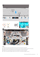
Steps 1. Align the screw holes on the system board with the screw holes on the palm-rest and keyboard assembly. 2. Hold the system board by the short edges, as shown in the image, and place the system board on the palm-rest and keyboard assembly. Ensure that the Thunderbolt 4 ports are aligned with their corresponding port holes on the palm-rest and keyboard assembly. 3. Replace the seven screws (M1.6x2.3) that secure the system board to the palm-rest and keyboard assembly. 4. Replace the four screws (M1.6x3) that secure the system board to the palm-rest and keyboard assembly. 5. Connect the power-button cable and close the latch of the power-button connector. 6. Connect the right-speaker cable. 7. Connect the keyboard control-board cable and close the latch of the keyboard control-board connector. 8. Connect the touchpad cable and close the latch of the touchpad connector. 9. Connect the left-speaker cable. 10. Connect the capacitive touch-panel cable and close the latch of the capacitive touch-panel connector. 11. Connect the camera cable and the display cable to the system board. 12. Connect the wireless-module cables from the wireless module. 13. Replace the display-assembly cable bracket on the system board. 14. Tighten the three captive screws (M1.6x2) that secure the display-assembly cable bracket to the system board. 15. Replace the wireless-module bracket on the system board. 16. Tighten the captive screw (M1.6x2.3) that secures the wireless-module bracket to the system board. Next steps 1. Install the heat sink. 2. Install the fans. 3. Install the battery. 4. Install the M.2 2230 solid-state drive or M.2 2280 solid-state drive from M.2 slot, whichever applicable. 5. Install the base cover. 38 Removing and installing components
-
 1
1 -
2
-
3
-
4
-
5
-
6
-
7
-
8
-
9
-
10
-
11
-
12
-
13
-
14
-
15
-
16
-
17
-
18
-
19
-
20
-
21
-
22
-
23
-
24
-
25
-
26
-
27
-
28
-
29
-
30
-
31
-
32
-
 33
33 -
 34
34 -
 35
35 -
 36
36 -
 37
37 -
 38
38 -
 39
39 -
 40
40 -
 41
41 -
 42
42 -
 43
43 -
44
-
45
-
46
-
47
-
48
-
49
-
50
-
51
-
52
-
53
-
54
-
55
-
56
-
57
-
58
-
59
-
60
-
61
-
62
-
63
-
64
-
65
-
66
-
67
-
68
-
69
-
70
 |
 |
