Dewalt DW08802CG Instruction Manual - Page 9
Turning the Laser On, Checking Laser Accuracy
 |
View all Dewalt DW08802CG manuals
Add to My Manuals
Save this manual to your list of manuals |
Page 9 highlights
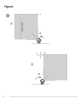
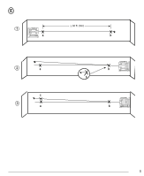
Turning the Laser On • Mark the center of the laser beam. E 1. Place the laser on a smooth, flat, level surface, with the laser facing straight ahead toward the opposing wall (0º position). 2. Turn the laser ON to display the horizontal and vertical laser beams. Either: Horizontal Beam - Scan Direction Checking the horizontal scan calibration of the laser requires two walls at least 30′ (9m) apart. It is important to conduct a calibration check using a distance no shorter than the distance of the applications for which the tool will be used. • Move the Power/Transport Lock switch to the left to keep the pendulum locked and display the cross beams in manual mode (Figure A 1 ). • Move the Power/Transport Lock switch to the right to unlock the pendulum and display the cross beams in self-leveling mode (Figure A 3 ). 3. Check the horizontal and vertical laser beams. • If the laser is tilted so much that it cannot self-level (> 4°), or the laser is not level in manual mode, the laser beams will flash. • If the laser beams flash, the laser is not level (or plumb) and should NOT BE USED for determining or marking level or plumb. Try repositioning the laser on a level surface. 1. Place the back of the laser against a wall and facing straight ahead toward the opposing wall (Figure D 1 ). 2. Move the Power/Transport Lock switch to the right (Figure A 3 ) to turn the laser ON in self-leveling mode and display the horizontal and vertical beams. 3. Turn the laser 45º counter-clockwise so that the right-most end of the laser line is displayed on the wall. 4. Mark a on the center of the beam on the wall. 5. Turn the laser 90º clockwise so that the left-most end of the laser line is displayed near a (Figure D 2 ). 6. Mark b on the center of the beam on the wall. 7. Measure the vertical distance between a and b . 4. If ANY of the following statements are TRUE, continue with 8. If your measurement is greater than the Allowable the instructions for Checking Laser Accuracy BEFORE Distance Between a and b for the corresponding USING THE LASER for a project. Distance Between Walls in the following table, the laser • This is the first time you are using the laser (in case the must be serviced at an authorized service center. laser was exposed to extreme temperatures). Distance Allowable Distance • The laser has not been checked for accuracy in Between Walls Between a and b a while. 30′ (9m) 15/32" (12mm) • The laser may have been dropped. 40′ (12m) 9/16" (14.4mm) Checking Laser Accuracy 50′ (15m) 23/32" (18mm) Horizontal Beam - Pitch Direction The laser tools are sealed and calibrated at the factory. It is recommended that you perform an accuracy check prior to using the laser for the first time (in case the laser was exposed to extreme temperatures) and then regularly to ensure the accuracy of your work. When performing any of the accuracy checks listed in this manual, follow these guidelines: • Use the largest area/distance possible, closest to the operating distance. The greater the area/distance, the easier to measure the accuracy of the laser. • Place the laser on a smooth, flat, stable surface that is level in both directions. Checking the horizontal pitch calibration of the laser requires a single wall at least 30′ (9m) long. It is important to conduct a calibration check using a distance no shorter than the distance of the applications for which the tool will be used. 1. Place the laser against the end of the wall (Figure E 1 ). 2. Move the Power/Transport Lock switch to the right (Figure A 3 ) to turn the laser ON in self-leveling mode and display the horizontal and vertical beams. 3. At least 30′ (9m) apart along the laser beam, mark a and b. 9
-
 1
1 -
2
-
3
-
 4
4 -
 5
5 -
 6
6 -
 7
7 -
 8
8 -
 9
9 -
 10
10 -
 11
11 -
 12
12 -
 13
13 -
 14
14 -
15
-
16
-
17
-
18
-
19
-
20
-
21
-
22
-
23
-
24
-
25
-
26
-
27
-
28
-
29
-
30
-
31
-
32
-
33
-
34
 |
 |
