E-Z-GO RXV - Gas Owner Manual - Page 22
Before Initial Use, Controls And Indicators
 |
View all E-Z-GO RXV - Gas manuals
Add to My Manuals
Save this manual to your list of manuals |
Page 22 highlights
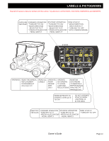
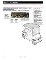
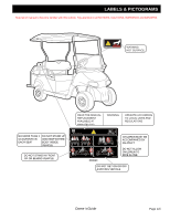
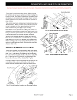
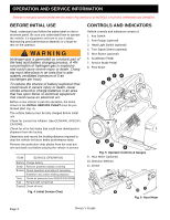
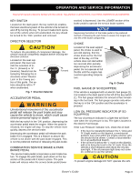
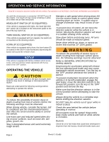
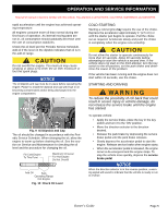
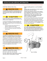
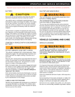
OPERATION AND SERVICE INFORMATION Read all of manual to become familiar with this vehicle. Pay attention to all NOTICES, CAUTIONS, WARNINGS and DANGERS. BBEFORE INITIAL USE Read, understand and follow the safety label on the instrument panel. Be sure you understand how to operate the vehicle, it's equipment and how to use it safely. Maintaining good performance depends to a large extent on the operator. Hydrogen gas is generated as a natural part of the lead acid battery charging process. A 4% concentration of hydrogen gas is explosive and could cause severe injury or death. Charging must take place in an area that is adequately ventilated (minimum of 5 air exchanges per hour). To reduce the chance of battery explosion that could result in severe injury or death, never smoke around or charge batteries in an area that has open flame or electrical equipment that could cause an electrical arc. Before a new vehicle is put into operation, the items shown in the INITIAL SERVICE CHART must be performed (Ref. Fig. 4). The vehicle battery must be fully charged before initial use. Check for correct tire inflation. See GENERAL SPECIFICATIONS. Check for oil or fuel leaks that could have developed in shipment from the factory. Determine and record the braking distance required to stop the vehicle for future brake performance tests. Remove the protective clear plastic from the seat bottom and back rest before placing the vehicle in service . ITEM SERVICE OPERATION Battery Charge battery Seats Remove protective plastic covering Brakes Check operation and adjust if necessary Establish new vehicle braking distance Tires Check air pressure (see SPECIFICATIONS) Fuel Fill tank with correct fuel Engine Check oil level Fig. 4 Initial Service Chart CONTROLS AND INDICATORS Vehicle controls and indicators consist of: 1. Key Switch 2. Fuel Gauge (optional) 3. Head Light Switch (optional) 4. Turn Signal Switch (optional) 5. Horn Button (optional) 6. Accelerator Pedal 7. Service Brake Pedal 8. Park Brake Fig. 5 Operator Controls & Gauges 9. Hour Meter (optional) 10. Direction Selector 11. Choke Fig. 6 Hour Meter Page 2 Owner's Guide
-
 1
1 -
2
-
3
-
4
-
5
-
6
-
7
-
8
-
9
-
10
-
11
-
12
-
13
-
14
-
15
-
16
-
 17
17 -
 18
18 -
 19
19 -
 20
20 -
 21
21 -
 22
22 -
 23
23 -
 24
24 -
 25
25 -
 26
26 -
 27
27 -
28
-
29
-
30
-
31
-
32
-
33
-
34
-
35
-
36
-
37
-
38
-
39
-
40
-
41
-
42
-
43
-
44
-
45
-
46
-
47
-
48
-
49
-
50
-
51
-
52
-
53
-
54
-
55
-
56
-
57
-
58
-
59
-
60
 |
 |
