Esoteric Grandioso D1 Owners Manual EN FR SP - Page 11
Names and functions of parts (display
 |
View all Esoteric Grandioso D1 manuals
Add to My Manuals
Save this manual to your list of manuals |
Page 11 highlights
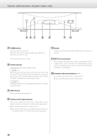
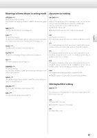
English Names and functions of parts (display) a b cd L c h DSD DIRECT MCK IN 10MHz ESLINK 352 e f a Channel This shows the channel played back by this unit (page 15). No indicator: No channel has been set for this unit. Use this setting only with mono output from a source device. Lch: This unit is set to the front left channel. By connecting the L-R connectors of this unit and the D1 set to Rch, they can share various settings and during stereo output the right channel audio signal from the audio source device can be sent to the Rch D1. Rch: This unit is set to the front right channel. By connecting the L-R connectors of this unit and the D1 set to Lch, they can share various settings and during stereo output the right channel audio signal from the audio source device can be sent to this unit for playback. b Upconversion setting No indicator: The upconversion function is not in use. UPCONV 2Fs: The upconverter circuit will upconvert the signal to 64, 88.2 or 96 kHz before digital to analog conversion. UPCONV 4Fs: The upconverter circuit will upconvert the signal to 128, 176.4 or 192 kHz before digital to analog conversion. UPCONV 8Fs: The upconverter circuit will upconvert the signal to 256, 352.8 or 384 kHz before digital to analog conversion. UPCONV DSD: The upconverter circuit will convert the PCM signal to a DSD signal before digital to analog conversion. DSD DIRECT: If DSD_F (DSD filter) is set to OFF, this appears when a DSD signal is input. oo Even if the upconverter is set, the upconverter might not be usable depending on the input source sampling frequency conditions. oo You can make settings as you like for each input. oo When ES-LINK input is selected, this can only be set to OFF or DSD. c Clock mode No indicator: CLK is set to OFF. CLK OUT: Shown when CLK is set to OUT. The frequency display area shows the output clock frequency. CLK IN: Shown when CLK is set to IN. The frequency display area shows the input clock frequency. MCK IN: Shown when CLK is set to MCK IN or MCK10M. The frequency display area shows the input clock frequency. INTERNAL: This is shown when unsynchronized signals are received during USB input. The frequency display area shows the master clock frequency being used. d Clock frequency e Input f Sampling frequency 11
-
 1
1 -
2
-
3
-
4
-
5
-
 6
6 -
 7
7 -
 8
8 -
 9
9 -
 10
10 -
 11
11 -
 12
12 -
 13
13 -
 14
14 -
 15
15 -
 16
16 -
17
-
18
-
19
-
20
-
21
-
22
-
23
-
24
-
25
-
26
-
27
-
28
-
29
-
30
-
31
-
32
-
33
-
34
-
35
-
36
-
37
-
38
-
39
-
40
-
41
-
42
-
43
-
44
-
45
-
46
-
47
-
48
-
49
-
50
-
51
-
52
-
53
-
54
-
55
-
56
-
57
-
58
-
59
-
60
 |
 |
