Esoteric Grandioso D1 Owners Manual EN FR SP - Page 15
Clock input connector selection, Clock output settings, Playback channel setting
 |
View all Esoteric Grandioso D1 manuals
Add to My Manuals
Save this manual to your list of manuals |
Page 15 highlights
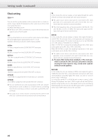
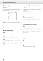
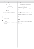
English Clock input connector selection Playback channel setting CLKin>*** CH>*** Use this to select the clock input connector. CLK In this mode, this unit can receive a clock signal through its CLOCK SYNC IN connector from a clock generator and operate with clock synchronization. oo The input impedance of the CLOCK SYNC IN connector is 75 Ω, so TTL-level square wave signals can be input. 10M In this mode, this unit can receive a 10MHz clock signal from a clock generator connected to its 10MHz IN connector and operate with clock synchronization. oo The audio source device must also be connected to the clock generator or be connected to this unit's CLOCK SYNC OUT connector and set to receive clock synchronization. oo The input impedance of the 10MHz IN connector is 50 Ω, so sine wave signals can be input. This shows the channel played back by this unit. By default, this is set to "CH> - - -". Use this setting when only connected to a P1 as a dedicated system. (Use with ES-LINK or XLR_DUAL connections.) When connecting to digital input connectors in modes other than ES-LINK and XLR_DUAL and using the left and right channel transmission (L-R) connectors, use one of the following settings. - - The channel used is not set. Only use this when connecting a P1 or other source device that can output left and right signals as mono. Using L-R LINK is not necessary. Lch Use to play back the left channel. The right channel data will be output from the L-R connector. Rch Use to play back the right channel. The right channel data will be input through the L-R connector. Clock output settings CLK_TH>*** This sets the clock output during clock input mode. OFF No clocks signal is output from the CLOCK SYNC OUT connector. ON The input clock signal is output from the CLOCK SYNC OUT connector as clock with the same frequency. oo When using input other than ES-LINK or DUAL, connect this unit to the D1 set as the left channel. The various settings made for the left channel will be reflected by the right channel settings. 15
-
 1
1 -
2
-
3
-
4
-
5
-
6
-
7
-
8
-
9
-
 10
10 -
 11
11 -
 12
12 -
 13
13 -
 14
14 -
 15
15 -
 16
16 -
 17
17 -
 18
18 -
 19
19 -
 20
20 -
21
-
22
-
23
-
24
-
25
-
26
-
27
-
28
-
29
-
30
-
31
-
32
-
33
-
34
-
35
-
36
-
37
-
38
-
39
-
40
-
41
-
42
-
43
-
44
-
45
-
46
-
47
-
48
-
49
-
50
-
51
-
52
-
53
-
54
-
55
-
56
-
57
-
58
-
59
-
60
 |
 |
