Fisher and Paykel OR36SCG6R1 Installation Guide - Page 16
Electrical Connection
 |
View all Fisher and Paykel OR36SCG6R1 manuals
Add to My Manuals
Save this manual to your list of manuals |
Page 16 highlights
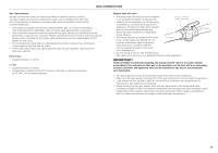
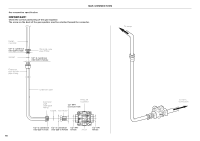
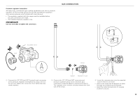
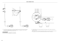
PERMANENT CONNECTION (HARD WIRING) US only, for Canada it is mandatory to connect the range by using cordset with plug supplied. z Units may be hard wired to the power supply. The installer must provide approved flexible aluminium conduit, 3/4" (19mm) trade size, maximum 6ft (1.8m) long. Locate the terminal block on the rear of the unit and remove access cover. z The strain relief bracket orientation must be switched in order to accommodate for a permanent wiring connection: 1 Remove the factory supplied power cord with plug. 2 Remove the 2 screws on the bracket. 3 Re-secure bracket with the 2 screws so that the 1 1/8" (29mm) smaller opening is facing down. Terminal Block ELECTRICAL CONNECTION 4-Wire Connection 1 Loosen the L1 (black), L2 (red) and neutral (white) screws. 2 Mount the conduit fitting to the 1 1/8" (29mm) hole in the strain relief bracket. 3 Secure the neutral (white) power lead to the center terminal and tighten the screw. 4 Secure the L1 (black) and the L2 (red) power leads to the terminals immediately to the left (L1) and right (L2) of the neutral terminal. Tighten the screws. 5 Secure the Ground (green) lead to the green screw located to the right of the terminal block using the supplied cupped washer. The end of the grounding conductor must be retained by the cupped washer. 6 Check all connections are securely tightened. 7 Reinstall the Terminal Block cover. 3-Wire Connection (using supplied Ground lead) 1 Loosen the L1 (black), L2 (red) and neutral (white) screws. 2 Mount the conduit fitting to the 1 1/8" (29mm) hole in the strain relief bracket. 3 Secure the supplied Ground (green) lead to the grounding screw to the right of the terminal block. 4 Secure the Neutral (white) power lead together with the free end of the Ground (green) lead to the center terminal. Tighten the screw. 5 Secure the L1 (black) and the L2 (red) power leads to the terminals immediately to the left (L1) and right (L2) of the neutral terminal. Tighten the screws. 6 Check all connections are securely tightened. 7 Reinstall the Terminal Block cover. 11 22 33 Strain relief bracket Smaller opening z The conduit must be installed to the terminal block using an approved conduit connector. The free end of the conduit must be connected to a junction box provided in the electrical supply zone. z Mount a strain relief (not provided) into the 1 1/8" (29mm) diameter hole located below the terminal block. Wiring for the unit is to be brought into the terminal block through the conduit and through the strain relief. Make suitable connections to the terminal block provided. z Installer - Show the owner the location of the circuit breaker. Mark it for easy reference. L1 N L2 PE PE L1 N L2 16
-
 1
1 -
2
-
3
-
4
-
5
-
6
-
7
-
8
-
9
-
10
-
 11
11 -
 12
12 -
 13
13 -
 14
14 -
 15
15 -
 16
16 -
 17
17 -
 18
18 -
 19
19 -
 20
20 -
 21
21 -
22
-
23
-
24
-
25
-
26
-
27
-
28
-
29
-
30
-
31
-
32
-
33
-
34
-
35
-
36
-
37
-
38
-
39
-
40
-
41
-
42
-
43
-
44
-
45
-
46
-
47
-
48
-
49
-
50
-
51
-
52
-
53
-
54
-
55
-
56
 |
 |
