Fujitsu MAN3735MC Manual/User Guide - Page 63
Connection Requirements, 4.3.1 68 pin connector 16-bit SCSI model (MP model), SCSI MP model.
 |
View all Fujitsu MAN3735MC manuals
Add to My Manuals
Save this manual to your list of manuals |
Page 63 highlights
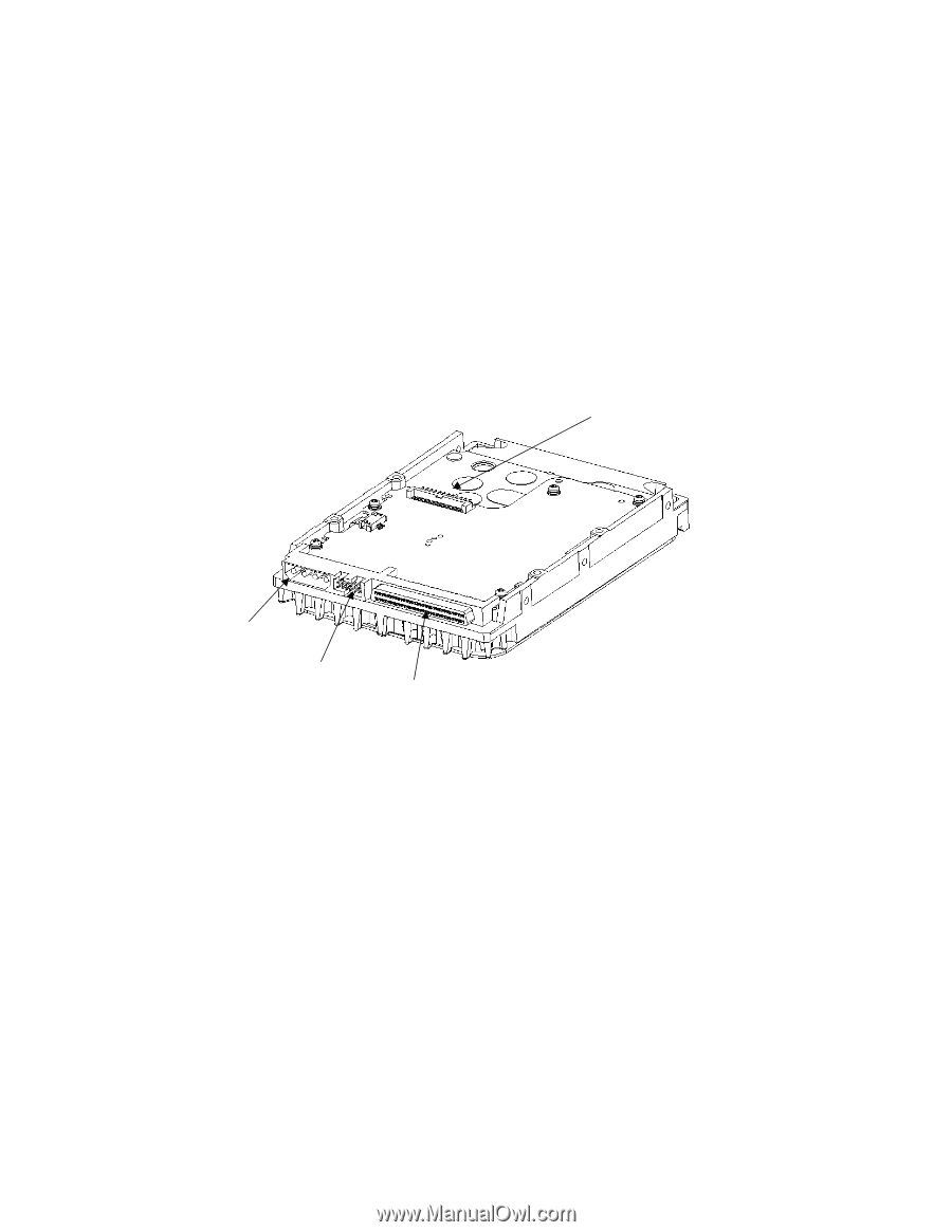
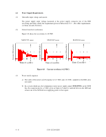
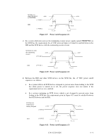
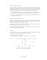
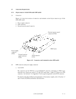
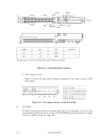
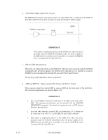
4.3 Connection Requirements 4.3.1 68 pin connector 16-bit SCSI model (MP model) (1) Connectors Figures 4.13 show the locations of connectors and terminals on the 68 pin connector type 16-bit SCSI (MP) model. • Power supply connector • SCSI connector • External operator panel connector External operator panel connector (CN2) Power supply connector (CN1) External operator panel connector (CN1) SCSI connector (CN1) MAN series Figure 4.13 Connectors and terminals location (MP model) (2) SCSI connector and power supply connector a. 16-bit SCSI The connector for the SCSI bus is an unshielded P connector conforming to SCSI-3 type which has two 34-pin rows spaced 1.27 mm (0.05 inch) apart. Figure 4.14 shows the SCSI connector. See Section C.2 in Appendix C for the signal assignments on the SCSI connector. For details on the physical/electrical requirements of the interface signals, refer to Sections 1.3 and 1.4 in the SCSI Physical Interface Specifications. C141-E128-01EN 4 - 11
-
 1
1 -
2
-
3
-
4
-
5
-
6
-
7
-
8
-
9
-
10
-
11
-
12
-
13
-
14
-
15
-
16
-
17
-
18
-
19
-
20
-
21
-
22
-
23
-
24
-
25
-
26
-
27
-
28
-
29
-
30
-
31
-
32
-
33
-
34
-
35
-
36
-
37
-
38
-
39
-
40
-
41
-
42
-
43
-
44
-
45
-
46
-
47
-
48
-
49
-
50
-
51
-
52
-
53
-
54
-
55
-
56
-
57
-
 58
58 -
 59
59 -
 60
60 -
 61
61 -
 62
62 -
 63
63 -
 64
64 -
 65
65 -
 66
66 -
 67
67 -
 68
68 -
69
-
70
-
71
-
72
-
73
-
74
-
75
-
76
-
77
-
78
-
79
-
80
-
81
-
82
-
83
-
84
-
85
-
86
-
87
-
88
-
89
-
90
-
91
-
92
-
93
-
94
-
95
-
96
-
97
-
98
-
99
-
100
-
101
-
102
-
103
-
104
-
105
-
106
-
107
-
108
-
109
-
110
-
111
-
112
-
113
-
114
-
115
-
116
-
117
-
118
-
119
-
120
-
121
-
122
-
123
-
124
-
125
-
126
-
127
-
128
-
129
-
130
-
131
-
132
-
133
-
134
-
135
-
136
-
137
-
138
-
139
-
140
-
141
-
142
-
143
-
144
-
145
 |
 |