Fujitsu MAN3735MC Manual/User Guide - Page 65
External operator panel connector CN1, shown
 |
View all Fujitsu MAN3735MC manuals
Add to My Manuals
Save this manual to your list of manuals |
Page 65 highlights
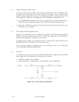
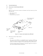
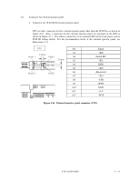
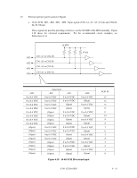
(4) Connector for external operator panel • Connector for 16-bit SCSI external operator panel CN1 provides connector for the external operator panel other than the SCSI bus as shown in Figure 4.16. Also, a connector for the external operator panel are provided on the IDD as shown in Figure 4.17. This allows connection of an external LED on the front panel, and an SCSI ID setting switch. For the recommended circuit of the external operator panel, see Subsection 4.3.4. Pin Signal A1 -ID0 A2 Fault LED A3 -ID1 A4 ESID A5 -ID2 A6 (Reserved) A7 -ID3 A8 -LED A9 OPEN A10 GND A11 +5 V A12 -WTP Figure 4.16 External operator panel connector (CN1) C141-E128-01EN 4 - 13
-
 1
1 -
2
-
3
-
4
-
5
-
6
-
7
-
8
-
9
-
10
-
11
-
12
-
13
-
14
-
15
-
16
-
17
-
18
-
19
-
20
-
21
-
22
-
23
-
24
-
25
-
26
-
27
-
28
-
29
-
30
-
31
-
32
-
33
-
34
-
35
-
36
-
37
-
38
-
39
-
40
-
41
-
42
-
43
-
44
-
45
-
46
-
47
-
48
-
49
-
50
-
51
-
52
-
53
-
54
-
55
-
56
-
57
-
58
-
59
-
 60
60 -
 61
61 -
 62
62 -
 63
63 -
 64
64 -
 65
65 -
 66
66 -
 67
67 -
 68
68 -
 69
69 -
 70
70 -
71
-
72
-
73
-
74
-
75
-
76
-
77
-
78
-
79
-
80
-
81
-
82
-
83
-
84
-
85
-
86
-
87
-
88
-
89
-
90
-
91
-
92
-
93
-
94
-
95
-
96
-
97
-
98
-
99
-
100
-
101
-
102
-
103
-
104
-
105
-
106
-
107
-
108
-
109
-
110
-
111
-
112
-
113
-
114
-
115
-
116
-
117
-
118
-
119
-
120
-
121
-
122
-
123
-
124
-
125
-
126
-
127
-
128
-
129
-
130
-
131
-
132
-
133
-
134
-
135
-
136
-
137
-
138
-
139
-
140
-
141
-
142
-
143
-
144
-
145
 |
 |

C141-E128-01EN
4 - 13
(4)
Connector for external operator panel
•
Connector for 16-bit SCSI external operator panel
CN1 provides connector for the external operator panel other than the SCSI bus as shown in
Figure 4.16.
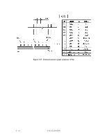
Also, a connector for the external operator panel are provided on the IDD as
shown in Figure 4.17.
This allows connection of an external LED on the front panel, and an
SCSI ID setting switch.
For the recommended circuit of the external operator panel, see
Subsection 4.3.4.
Figure 4.16
External operator panel connector (CN1)
Pin
Signal
A1
–ID0
A2
Fault LED
A3
–ID1
A4
ESID
A5
–ID2
A6
(Reserved)
A7
–ID3
A8
–LED
A9
OPEN
A10
GND
A11
+5 V
A12
–WTP