Fujitsu MAN3735MC Manual/User Guide - Page 79
Setting Terminals, MAN Series MP model only
 |
View all Fujitsu MAN3735MC manuals
Add to My Manuals
Save this manual to your list of manuals |
Page 79 highlights
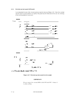
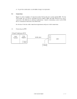
5.3 Setting Terminals A user sets up the following terminals and SCSI terminating resistor before installing the IDD in the system as required. • Setting terminal: CN2 (MP model only) Figures 5.2 shows the setting terminal position. Figures 5.3 shows the allocation and default settings. CAUTION Data loss 1. The user must not change the setting of terminals not described in this section. Do not change setting status set at factory shipment. 2. Do not change the setting of terminals except following setting pins during the power is turned on. • Write protect: CN2 9-10 (MP model only) 3. To short the setting terminal, use the short plug attached when the device is shipped from the factory. CN1 CN2 Pin 1 MAN Series (MP model only) Figure 5.2 IDD setting terminals position C141-E128-01EN 5 - 5
-
 1
1 -
2
-
3
-
4
-
5
-
6
-
7
-
8
-
9
-
10
-
11
-
12
-
13
-
14
-
15
-
16
-
17
-
18
-
19
-
20
-
21
-
22
-
23
-
24
-
25
-
26
-
27
-
28
-
29
-
30
-
31
-
32
-
33
-
34
-
35
-
36
-
37
-
38
-
39
-
40
-
41
-
42
-
43
-
44
-
45
-
46
-
47
-
48
-
49
-
50
-
51
-
52
-
53
-
54
-
55
-
56
-
57
-
58
-
59
-
60
-
61
-
62
-
63
-
64
-
65
-
66
-
67
-
68
-
69
-
70
-
71
-
72
-
73
-
 74
74 -
 75
75 -
 76
76 -
 77
77 -
 78
78 -
 79
79 -
 80
80 -
 81
81 -
 82
82 -
 83
83 -
 84
84 -
85
-
86
-
87
-
88
-
89
-
90
-
91
-
92
-
93
-
94
-
95
-
96
-
97
-
98
-
99
-
100
-
101
-
102
-
103
-
104
-
105
-
106
-
107
-
108
-
109
-
110
-
111
-
112
-
113
-
114
-
115
-
116
-
117
-
118
-
119
-
120
-
121
-
122
-
123
-
124
-
125
-
126
-
127
-
128
-
129
-
130
-
131
-
132
-
133
-
134
-
135
-
136
-
137
-
138
-
139
-
140
-
141
-
142
-
143
-
144
-
145
 |
 |
