Gateway E-9425R Gateway E-9425R Server User Guide - Page 47
Replacing system fans
 |
View all Gateway E-9425R manuals
Add to My Manuals
Save this manual to your list of manuals |
Page 47 highlights
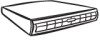
www.gateway.com 10 Insert the new PCI card into the riser card, making sure any connectors extend through the slot at the back of the assembly and that the card is fully seated in the riser card. 11 Close the lock to hold the card in place, then replace the screw that holds the lock closed. 12 Position the PCI riser assembly over the PCI sockets on the server board, Then press the PCI riser assembly into the PCI sockets. 13 Follow the instructions in "Closing the server case" on page 30. 14 See the card's documentation for software installation instructions. Replacing system fans This server contains six groups of hot-swappable, dual-rotor fans (seated in the fan cage) and a fan board, which are located inside the chassis. These fans maintain the ideal temperature for the system board, backplane, and disk drives. If one fan fails, the speed of the other fans will increase. With the bad fan replaced, the other fans may revert to normal speed. To replace a fan group: 1 Follow the instructions in "Preventing static electricity discharge" on page 28. 2 Follow the instructions in "Opening the server case" on page 29. System fan location 3 Note which fan group is not working and therefore needs to be replaced. Important Make sure that the arrows on top of the fans indicating airflow point to the back of the chassis. The fan cable should exit the fan module toward the back of the chassis. 4 Disconnect the 6-pin fan tach cable from the fan board. 5 Lift the fan group from the fan cage in the chassis. 6 Insert the replacement fan group into the fan cage. 7 Connect the 6-pin fan tach cable from the fan to the fan board. 8 Follow the instructions in "Closing the server case" on page 30. 41
-
 1
1 -
2
-
3
-
4
-
5
-
6
-
7
-
8
-
9
-
10
-
11
-
12
-
13
-
14
-
15
-
16
-
17
-
18
-
19
-
20
-
21
-
22
-
23
-
24
-
25
-
26
-
27
-
28
-
29
-
30
-
31
-
32
-
33
-
34
-
35
-
36
-
37
-
38
-
39
-
40
-
41
-
 42
42 -
 43
43 -
 44
44 -
 45
45 -
 46
46 -
 47
47 -
 48
48 -
 49
49 -
 50
50 -
 51
51 -
 52
52 -
53
-
54
-
55
-
56
-
57
-
58
-
59
-
60
-
61
-
62
-
63
-
64
-
65
-
66
-
67
-
68
-
69
-
70
-
71
-
72
-
73
-
74
-
75
-
76
-
77
-
78
-
79
-
80
-
81
-
82
-
83
-
84
-
85
-
86
-
87
-
88
-
89
-
90
-
91
-
92
-
93
-
94
-
95
-
96
-
97
-
98
-
99
-
100
-
101
-
102
-
103
-
104
-
105
-
106
-
107
-
108
-
109
-
110
-
111
-
112
-
113
-
114
-
115
-
116
 |
 |
