Gigabyte GA-7TESH2-RH Manual - Page 14
Installation Steps, Dimma2, Dimma1, Dimmb2, Dimmb1, Dimmc2, Dimmc1, Dimmd2, Dimmd1, Dimme2, Dimme1,
 |
View all Gigabyte GA-7TESH2-RH manuals
Add to My Manuals
Save this manual to your list of manuals |
Page 14 highlights
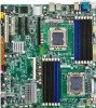
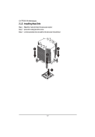
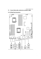
Hardware Installation Process Installation Steps: Step 1. Insert the DIMM memory module vertically into the DIMM slot, and push it down. Step 2. Close the plastic clip at both edges of the DIMM slots to lock the DIMM module. NOTE! DIMM must be populated in order starting from DIMMA1/D1 socket. For dual-channel operation, DIMMs must be installed in matched pairs. Step 3. Reverse the installation steps when you wish to remove the DIMM module. 1 2 2 DIMMF1 DIMME1 DIMMF2 DIMME2 DIMMD1 DIMMD2 CPU2 CPU1 DIMMA2 DIMMA1 DIMMB2 DIMMB1 DIMMC2 DIMMC1 14
-
 1
1 -
2
-
3
-
4
-
5
-
6
-
7
-
8
-
 9
9 -
 10
10 -
 11
11 -
 12
12 -
 13
13 -
 14
14 -
 15
15 -
 16
16 -
 17
17 -
 18
18 -
 19
19 -
20
-
21
-
22
-
23
-
24
-
25
-
26
-
27
-
28
-
29
-
30
-
31
-
32
-
33
-
34
-
35
-
36
-
37
-
38
-
39
-
40
-
41
-
42
-
43
-
44
-
45
-
46
-
47
-
48
-
49
-
50
-
51
-
52
-
53
-
54
-
55
-
56
-
57
-
58
-
59
-
60
-
61
-
62
-
63
-
64
-
65
-
66
-
67
-
68
-
69
-
70
-
71
-
72
-
73
-
74
-
75
 |
 |

14
Hardware Installation Process
Installation Steps:
Step 1.
Insert the DIMM memory
module vertically into the DIMM slot, and push it
down.
Step 2.
Close the plastic clip at both edges of the DIMM slots to lock the DIMM module.
NOTE!
DIMM must be populated in order starting from DIMMA1/D1 socket. For dual-channel
operation, DIMMs must be installed in matched pairs.
Step 3.
Reverse the installation steps when you wish to remove the DIMM module.
2
2
1
CPU1
CPU2
DIMMA2
DIMMA1
DIMMB2
DIMMB1
DIMMC2
DIMMC1
DIMMD2
DIMMD1
DIMME2
DIMME1
DIMMF2
DIMMF1