Gigabyte GA-7TESH2-RH Manual - Page 24
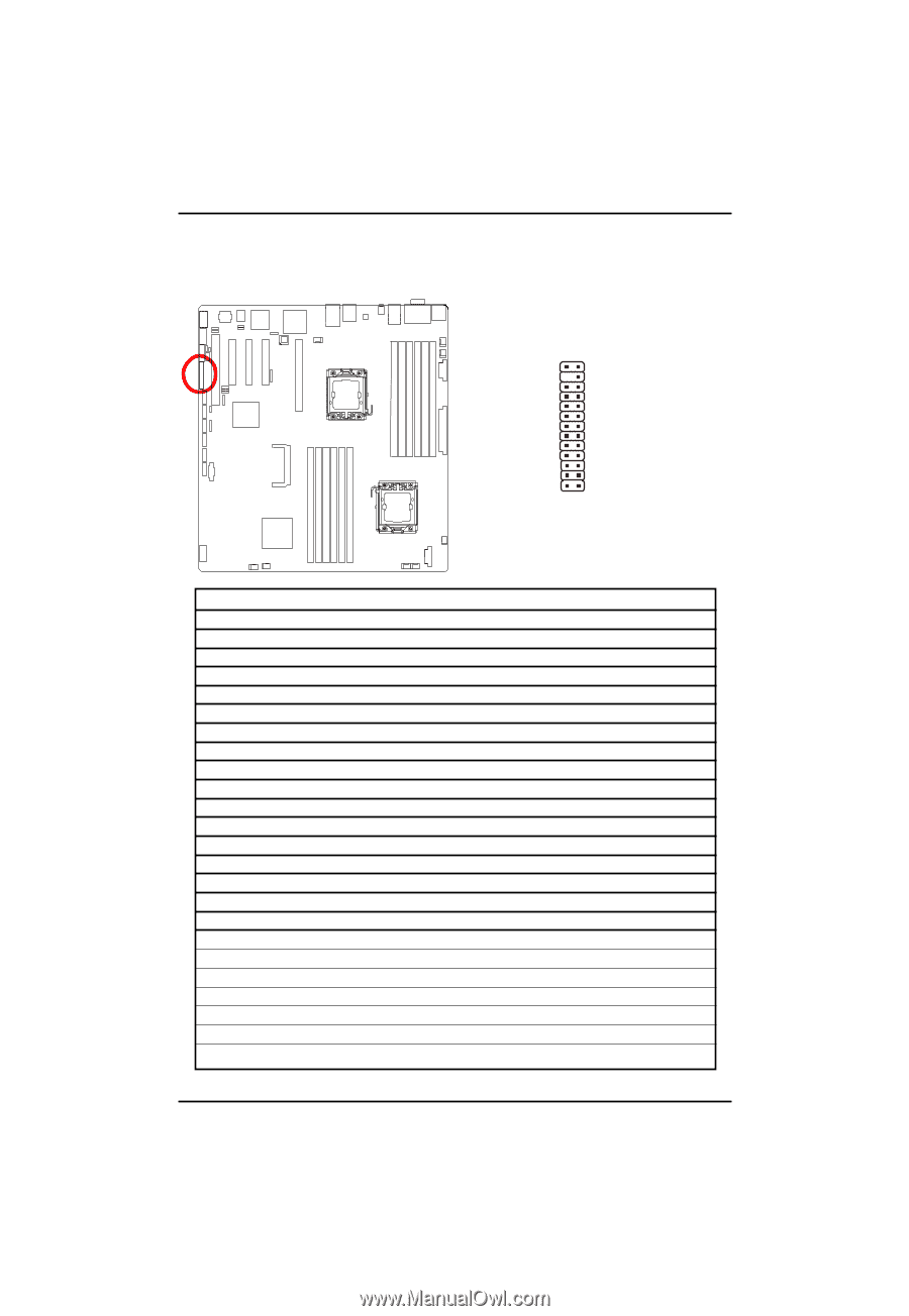
F_PANEL, 2X12 Pins Front Panel connector
 |
View all Gigabyte GA-7TESH2-RH manuals
Add to My Manuals
Save this manual to your list of manuals |
Page 24 highlights
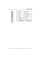
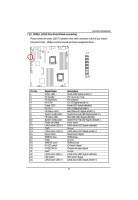
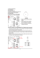
7 ) F_PANEL (2X12 Pins Front Panel connector) Connector Introduction Please connect the power LED, PC speaker, reset switch and power switch of your chassis front panel to the F_PANEL connector according to the pin assignment above. 12 23 24 Pin No. 1. 2. 3. 4. 5. 6. 7. 8. 9. 10. 11. 12. 13. 14. 15. 16. 17. 18. 19. 20. 21. 22. 23. 24. Signal Name Power LED + 5V standby Pin reomoved ID LED+ Power LED ID LED HD status LED+ System ready LED+ HD status LEDSystem ready LEDPower on switch LAN1 active LED (-) GND LAN1 active LED (+) Reset switch SMBUS data GND SMBUS clock ID LED switch CASEOPEN GND LAN2 active LED (-) NMI switch LAN2 active LED (+) Description Power LED Signal anode (+) P5V Stand By Power Pin removed ID LED Signal anode (+) Power LED Signal cathode(-) ID LED Signal cathode(-) Hard Disk LED Signal anode (+) System Fan Fail LED Signal anode (+) Hard Disk LED Signal cathode(-) System Fan Fail LED Signal cathode(-) Power button LAN1 active LED Signal cathode(-) Ground LAN1 active LED Signal anode (+) Reset button Signal SMBusData Ground SMBusClock ID Switch Signal Chassis intrusion Signal Ground LAN2 active LED Signal cathode(-) NMI switch Signal LAN2 active LED Signal anode (+) 24
-
 1
1 -
2
-
3
-
4
-
5
-
6
-
7
-
8
-
9
-
10
-
11
-
12
-
13
-
14
-
15
-
16
-
17
-
18
-
 19
19 -
 20
20 -
 21
21 -
 22
22 -
 23
23 -
 24
24 -
 25
25 -
 26
26 -
 27
27 -
 28
28 -
 29
29 -
30
-
31
-
32
-
33
-
34
-
35
-
36
-
37
-
38
-
39
-
40
-
41
-
42
-
43
-
44
-
45
-
46
-
47
-
48
-
49
-
50
-
51
-
52
-
53
-
54
-
55
-
56
-
57
-
58
-
59
-
60
-
61
-
62
-
63
-
64
-
65
-
66
-
67
-
68
-
69
-
70
-
71
-
72
-
73
-
74
-
75
 |
 |