Gigabyte GA-7TESH2-RH Manual - Page 28
SGPIO_JP1 ICH10 SGPIO connector, J3 SMBus connector for B/P board
 |
View all Gigabyte GA-7TESH2-RH manuals
Add to My Manuals
Save this manual to your list of manuals |
Page 28 highlights
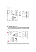
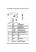
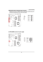
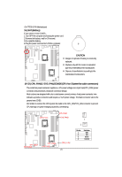
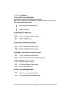
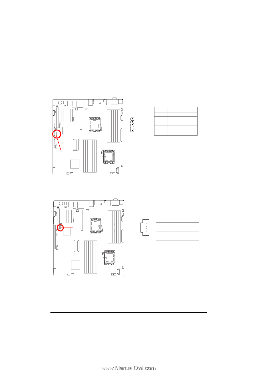
English GA-7TESH2-RH Motherboard 26 ) SGPIO_JP1 (ICH10 SGPIO connector) SGPIO is stands for Serial General Purpose Input/Output which is a 4-signal (or 4-wire) bus used between a Host Bus Adapter (HBA) and a backplane. Out of the 4 signals, 3 are driven by the HBA and 1 is driven by the backplane. Typically, the HBA is a storage controller located inside a server, desktop, rack or workstation computer that interfaces with Hard disk drives (HDDs) to store and retrieve data. SGPIO_JP1 Pin No. Definition 1 GND 2 NC 3 ICH_SATA_SDATA0 4 ICH_SATA_SLOAD 5 ICH_SATA_SCLOCK 1 SGPIO_JP1 27 ) J3 (SMBus connector for B/P board) 1 Pin No. Definition J3 1 GND 2 P5V_AUX 3 R_SDA 4 R_SCL 28
-
 1
1 -
2
-
3
-
4
-
5
-
6
-
7
-
8
-
9
-
10
-
11
-
12
-
13
-
14
-
15
-
16
-
17
-
18
-
19
-
20
-
21
-
22
-
 23
23 -
 24
24 -
 25
25 -
 26
26 -
 27
27 -
 28
28 -
 29
29 -
 30
30 -
 31
31 -
 32
32 -
 33
33 -
34
-
35
-
36
-
37
-
38
-
39
-
40
-
41
-
42
-
43
-
44
-
45
-
46
-
47
-
48
-
49
-
50
-
51
-
52
-
53
-
54
-
55
-
56
-
57
-
58
-
59
-
60
-
61
-
62
-
63
-
64
-
65
-
66
-
67
-
68
-
69
-
70
-
71
-
72
-
73
-
74
-
75
 |
 |
28
English
GA-7TESH2-RH Motherboard
26 ) SGPIO_JP1 (ICH10 SGPIO connector)
1
Pin No.
Definition
1
GND
2
NC
3
ICH_SATA_SDATA0
4
ICH_SATA_SLOAD
5
ICH_SATA_SCLOCK
SGPIO_JP1
27 ) J3 (SMBus connector for B/P board)
J3
1
Pin No.
Definition
1
GND
2
P5V_AUX
3
R_SDA
4
R_SCL
SGPIO is stands for Serial General Purpose Input/Output which is a 4-signal (or 4-wire) bus used
between a Host Bus Adapter (HBA) and a backplane. Out of the 4 signals, 3 are driven by the
HBA and 1 is driven by the backplane. Typically, the HBA is a storage controller located inside a
server, desktop, rack or workstation computer that interfaces with Hard disk drives (HDDs) to
store and retrieve data.
SGPIO_JP1