Gigabyte GA-7TESH2-RH Manual - Page 26
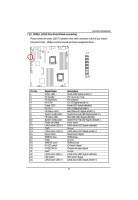
CPU_FAN1/2 / SYS_FAN1/2/3/4/5/6 CPU, fan / System fan cable connectors, BAT Battery, CAUTION
 |
View all Gigabyte GA-7TESH2-RH manuals
Add to My Manuals
Save this manual to your list of manuals |
Page 26 highlights
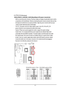
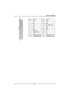
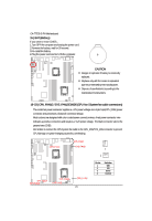
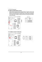
English GA-7TESH2-RH Motherboard 15 ) BAT (Battery) If you want to erase CMOS... 1.Turn OFF the computer and unplug the power cord. 2.Remove the battery, wait for 30 second. 3.Re-install the battery. 4.Plug the power cord and turn ON the computer. CAUTION Danger of explosion if battery is incorrectly replaced. Replace only with the same or equivalent type recommended by the manufacturer. Dispose of used batteries according to the manufacturer's instructions. 16~23 ) CPU_FAN1/2 / SYS_FAN1/2/3/4/5/6 (CPU fan / System fan cable connectors) The cooler fan power connector supplies a +12V power voltage via a 3-pin/4-pin(CPU_FAN) power connector and possesses a foolproof connection design. Most coolers are designed with color-coded power connector wires. A red power connector wire indicates a positive connection and requires a +12V power voltage. The black connector wire is the ground wire (GND). Remember to connect the CPU/system fan cable to the CPU_FAN/SYS_FAN connector to prevent CPU damage or system hanging caused by overheating. CPU2 FAN SYS FAN5 SYS FAN6 1 1 SYS FAN3 SYS FAN4 SYS FAN1 SYS FAN2 CPU1 FAN 26 Pin No. 1 2 3 4 Definition GND 12V Sense Control
-
 1
1 -
2
-
3
-
4
-
5
-
6
-
7
-
8
-
9
-
10
-
11
-
12
-
13
-
14
-
15
-
16
-
17
-
18
-
19
-
20
-
 21
21 -
 22
22 -
 23
23 -
 24
24 -
 25
25 -
 26
26 -
 27
27 -
 28
28 -
 29
29 -
 30
30 -
 31
31 -
32
-
33
-
34
-
35
-
36
-
37
-
38
-
39
-
40
-
41
-
42
-
43
-
44
-
45
-
46
-
47
-
48
-
49
-
50
-
51
-
52
-
53
-
54
-
55
-
56
-
57
-
58
-
59
-
60
-
61
-
62
-
63
-
64
-
65
-
66
-
67
-
68
-
69
-
70
-
71
-
72
-
73
-
74
-
75
 |
 |
