Harman Kardon AVR85 Owners Manual - Page 10
Signal Level Indication - review
 |
View all Harman Kardon AVR85 manuals
Add to My Manuals
Save this manual to your list of manuals |
Page 10 highlights
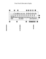
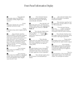
Front Panel Information Display 7 A AC-3 Indicator: This indicator illuminates when the AVR85 is decoding a Dolby Digital input source. B Surround Mode Status: These indicators display the currently selected surround mode. C Digital Mode Indicators: These indicators show which digital input is in use. D Multi: This indicator signifies that the AVR85 is sending a program source to a remote room location. Note that it may be illuminated even when the unit is "off" in the main listening room, signifying that operation continues at another location. When a remote command is being received via the Multi IR connection b, this indicator will flash. E Sleep Indicator: This indicator lights when the AVR85 is in the Sleep mode. F Night Indicator: This indicator lights when the AVR85 is in the Night mode, which prevents the AVR85 from loud playback when digital sources are in use. G P-Scan: This indicator flashes when the stations programmed into the tuner memory are being automatically reviewed. H LFE Indicator: This indicator will illuminate when the Low-Frequency Effects (LFE) option has been turned on through the controls in SETUP MENU 3. I DISP: This indicator lights when the FL display has been turned off using the Display button p to remind you that the unit is still turned on. J ATT Indicator: This indicator lights when the Attenuation function has been engaged to cut the input from analog sources by approximately 50%. K Main Information Display: This ten-digit display shows messages relating to the status, input source, surround mode, tuner, volume level or other aspects of unit's operation. L Stereo: This indicator lights when an FM station is broadcasting in stereo. M Tuned: This indicator lights when an AM or FM station is properly tuned and locked. N Auto: This indicator signifies that the Automatic Tuning mode is in use for FM broadcasts. O Memo: This indicator flashes when the Memo button is pressed when entering presets and other information into the tuner's memory. P Test: This indicator flashes when the output levels are being set using the built-in test signal generator. Q "Visual" Indicator: These indicators display which input source is being fed to the video monitor output. R PCM Indicator: This indicator illuminates to show that a standard PCM (SP/DIF) digital audio signal is being decoded by the digital-toanalog converter. S Signal Level Indication: This is a visual indication of the strength of a radio station signal. The more bars visible, the stronger the station.
-
 1
1 -
2
-
3
-
4
-
 5
5 -
 6
6 -
 7
7 -
 8
8 -
 9
9 -
 10
10 -
 11
11 -
 12
12 -
 13
13 -
 14
14 -
 15
15 -
16
-
17
-
18
-
19
-
20
-
21
-
22
-
23
-
24
-
25
-
26
-
27
-
28
-
29
-
30
-
31
-
32
-
33
-
34
-
35
-
36
-
37
-
38
-
39
-
40
 |
 |
