Harman Kardon AVR85 Owners Manual - Page 28
On-Screen Display
 |
View all Harman Kardon AVR85 manuals
Add to My Manuals
Save this manual to your list of manuals |
Page 28 highlights
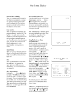
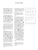
On-Screen Display 25 On-Screen Menus The AVR85's on-screen menu system provides both a window into the operation of the unit and a means of easily adjusting many system parameters. In addition to their use in the setup and configuration of the AVR85, the menu system provides an easy means of operating the unit. To activate the On-Screen display system, press the OSD button k on the remote for three seconds. This will cause a status summary display to be shown on the screen for ten seconds (see figure #6). Once the video displays are enabled, this status screen will also appear when the unit is turned on. Note: In order to view the on-screen menu displays the receiver must be connected to the standard, composite video input of a TV monitor or projector. The on-screen displays are NOT visible via the S-Video output. The status screen displays the following information: AUDIO SOURCE: This is the input currently selected for audio. VIDEO SOURCE: This is the input currently selected for video. TAPE MONITOR: If "ON" is displayed in this line the output of the AVR85 is the tape recorder connected to the Tape1 Inputs § rather than the actual source. This function is used to monitor a recording in progress. DIGITAL INPUT: If a digital audio source is selected, it is displayed here. MODE: This is the currently selected audio/surround mode. MULTI-ROOM: This is the source currently selected for listening in remote room locations. MASTER VOLUME: This is the current volume. The scale uses double vertical bars ± to indicate the volume level, - while single horizontal dashes indi- cate additional range available for increased volume. The "0dB" reference point is shown by a solid block Í. Function Displays and Messages Once the On-Screen Displays have been activated, they appear when certain functions are performed from the front panel buttons or the remote control. These messages display the current function shown on the top line and information about the selection or choice on the bottom line. The following function/operation display screens are available: Output Level Display and Adjust To view an on-screen summary of the output levels for each channel (see figure #9) press the Ch Select m. While this menu is displayed the output levels may be adjusted using the Speaker buttons n. Press the Ch Select button again to change the channel being adjusted. This screen enables adjustment of the output levels using an external source such as a test disc. This menu also provides a means of adjustment of the subwoofer output level which is not possible elsewhere in the control system. AUDIO SOURCE : VIDEO SOURCE : TAPE MONITOR : DIGITAL INPUT: TUNER VCR2 OFF ** MODE : DOLBY PRO LOGIC MULTI ROOM:TUNER MASTER VOLUME Figure 6 AUDIO:TUNER VIDEO:VCR1 DIGITAL:** Figure 7 MASTER VOLUME Figure 8 FRONT L FRONT R CENTER SURROUND L SURROUND R SUBWOOFER : + 1dB : - 2dB : + 1dB : -10dB : + 3dB : -10dB Figure 9 MODE DELAY :DOLBY PRO LOGIC TIME:20ms Figure 10
-
 1
1 -
2
-
3
-
4
-
5
-
6
-
7
-
8
-
9
-
10
-
11
-
12
-
13
-
14
-
15
-
16
-
17
-
18
-
19
-
20
-
21
-
22
-
 23
23 -
 24
24 -
 25
25 -
 26
26 -
 27
27 -
 28
28 -
 29
29 -
 30
30 -
 31
31 -
 32
32 -
 33
33 -
34
-
35
-
36
-
37
-
38
-
39
-
40
 |
 |
