Harman Kardon AVR85 Owners Manual - Page 12
S-Video RECORD/IN jacks of a VCR. - audio video receiver
 |
View all Harman Kardon AVR85 manuals
Add to My Manuals
Save this manual to your list of manuals |
Page 12 highlights
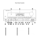
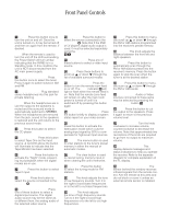
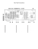
Rear Panel Connections 9 ¡ AM Antenna: Connect the AM loop antenna supplied with the receiver to these terminals. If an external AM antenna is used, make connections to the AM and GND terminals in accordance with the instructions supplied with the antenna. ™ FM Antenna: Connect an indoor or external FM antenna to this terminal. £ Tape 2 Out: Connect these jacks to the RECORD/INPUT jacks of a second audio recorder. ¢ Tape 2 In: Connect these jacks to the PLAY/OUT jacks of a second audio recorder. ∞ Tape 1 Out: Connect these jacks to the RECORD/INPUT jacks of an audio recorder. § Tape 1 In: Connect these jacks to the PLAY/OUT jacks of an audio recorder. ¶ CD IN: Connect these jacks to the output of a compact disc player or CD changer. • DVD Inputs: Connect the analog audio outputs and composite S-Video output of a DVD or LV player to these jacks. ª TV Inputs: Connect these jacks to the audio and video outputs of a TV Tuner, Cable TV converter box, satellite receiver, or any other audio/video source. , Pre-Outs: If external power amplifiers are used for any channels, connect them to these jacks ⁄ Subwoofer Pre-Out: Connect this jack to the line level input of a powered subwoofer. If an external subwoofer amplifier is used, connect this jack to the subwoofer amplifier input. ¤ Center: Connect these terminals to the center speaker. ‹ Surround: Connect these terminals to the surround speakers. › Front: Connect these terminals to the front speakers. fi Switched AC Outlet: This outlet may be used to power any device that you wish to have on when the unit is turned on. fl Unswitched AC Outlet: This outlet may be used to power any AC device. The power will remain on at this outlet regardless of whether the AVR85 is on or off. NOTE: The power consumption of the device plugged into each of these outlets should not exceed 120 watts. ‡ Power Cable: Connect the AC plug to a non-switched AC wall output. ° AC-3/PCM Optical Input: Connect the optical digital output from a DVD player, HDTV receiver, LV player or CD player to this jack. The signal may be either a Dolby Digital (AC-3) signal or a standard PCM digital source. · AC-3/PCM Coaxial Input: Connect the coax digital output from a DVD player, HDTV receiver, LV player or CD player to this jack. The signal may be either a Dolby Digital (AC-3) signal or a standard PCM digital source. a AC-3 RF Input: Connect the AC-3 RF output of an LV player equipped for digital audio to this jack. NOTE: Do not connect standard analog audio sources to these jacks. b Multi IR: Connect the output of an IR sensor in a remote room to this jack to operate the AVR85's multiroom control system. c Remote IR In: If the AVR85's front panel IR sensor is blocked due to cabinet doors or other obstructions, an external IR sensor may be used. Connect the output of the sensor to this jack. d Remote IR Out: This connection permits the IR sensor in the receiver to serve other remote controlled devices. Connect this jack to the "IR IN" jack on Harman Kardon or other compatible equipment. e VCR 1 Inputs: Connect these jacks to the audio, video and S-Video PLAY/OUT jacks of a VCR. f VCR 1 Outputs: Connect these jacks to the audio, video and S-Video RECORD/IN jacks of a VCR. g TV Monitor S-Video Output: Connect this jack to the S-Video input of a TV monitor or video projector to view S-Video sources selected by the receiver's video switcher. NOTE: Standard (composite) video and S-Video signals will appear only at their respective output. The AVR85 does not convert one video format to another. h TV Monitor Video Output: Connect this jack to the standard (composite) video input of a TV monitor or video projector to view the on-screen menus and the output of any standard video source selected by the receiver's video switcher. i Multiroom Audio Outputs: Connect these jacks to the optional audio power amplifier that powers remote room speakers with the input selected by the multiroom control system. j VCR 2 Outputs: Connect these jacks to the audio, video and S-Video RECORD/IN jacks of a second VCR. k VCR 2 Inputs: Connect these jacks to the audio, video and S-Video PLAY/OUT jacks of a second VCR.
-
 1
1 -
2
-
3
-
4
-
5
-
6
-
 7
7 -
 8
8 -
 9
9 -
 10
10 -
 11
11 -
 12
12 -
 13
13 -
 14
14 -
 15
15 -
 16
16 -
 17
17 -
18
-
19
-
20
-
21
-
22
-
23
-
24
-
25
-
26
-
27
-
28
-
29
-
30
-
31
-
32
-
33
-
34
-
35
-
36
-
37
-
38
-
39
-
40
 |
 |