Harman Kardon AVR85 Owners Manual - Page 17
System and Power Connections, External Audio Power, Amplifier Connections
 |
View all Harman Kardon AVR85 manuals
Add to My Manuals
Save this manual to your list of manuals |
Page 17 highlights
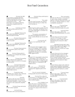
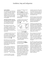
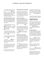
Installation, Setup and Configuration 14 7. Connections to a subwoofer are made via a line level audio connection from the Subwoofer Output ⁄ to the line level input of a subwoofer with a built-in amplifier. If a passive subwoofer is used, the connection first goes to a power amplifier, which will be connected to one or more subwoofer speakers. Video Input and Output Connections Video connections are made in a similar fashion to those for audio components. Again, the use of high-quality interconnect cables is recommended to preserve signal quality. 1. Connect the VCR's audio, video and S-Video OUT jacks to the Video In jacks e k on the rear panel. The audio, video and S-Video IN jacks on the VCR should be connected to the Video Out jacks f j on the AVR85. 2. Connect the audio and video outputs of a satellite receiver, cable TV converter or television set or any other video source to the TV jacks ª. 3. Connect the audio, video and S-Video outputs of a DVD or laser disc player to the DVD jacks •. 4. Connect the TV Mon g h jacks on the receiver to the video, or S-Video inputs, of your television monitor or video projector. 5. As the AVR85 does not mix or change between standard composite video and S-Video signals, both monitor connections must be made if you use both signal systems. Note: The on-screen menus are visible on the composite video output only. System and Power Connections The AVR85 is designed for flexible use with external control components and power amplifiers. These connections are easy to make during an initial installation, or at a later date should you choose to upgrade your system. Remote Control Extension If the receiver is placed behind a solid or smoked glass cabinet door, the obstruction may prevent the remote sensor from receiving commands. In this event, an optional remote sensor may be used. Connect the output of the remote sensor to the Remote Cont. In jack c. If other components are also prevented from receiving remote commands, only one sensor is needed. They may use this unit's sensor or a remote eye by running a connection from the Remote Cont. Out jack d to the Remote In jack on Harman Kardon or other compatible equipment. Multiroom System Connections The AVR85 is capable of sending a separate source from the one being listened to in the main listening room to another room in the house, and having the volume and source selection of the remote room feed be controlled by an optional infrared remote control. Connect the Multiroom Audio Outputs i to the input of the optional audio amplifier that powers the remote room speakers. If no remote sensor is connected in the second room zone, the level may be set via the AVR85's setup menus (see page 34). True multiroom remote control is possible by placing an optional infrared sensor in the second room zone. The cable from that sensor should be connected to the Multi IR remote input b on the rear panel. See page 34 for complete information on using the AVR85's Multiroom capabilities. External Audio Power Amplifier Connections If desired, optional external power audio power amplifiers may be used with the AVR85. Connections to these amplifiers are made by using audio interconnect cables connected to both the Preamp Outputs , on the rear panel and the audio input jacks of the external amplifiers. AC Power Connections This unit is equipped with two accessory AC outlets. They may be used to power accessory devices, but they should not be used with high-current draw equipment such as power amplifiers. The total power draw may not exceed 50w to each outlet. The Switched fi outlet will receive power only when the unit is on. This is recommended for devices that have no power switch, or a mechanical power switch that may be left in the "ON" position. Note: Devices with electronic power switches may only go into a Standby mode when plugged in here. The Unswitched fl outlet will receive power as long as the unit is plugged into a powered AC outlet. Finally, when all connections are complete, plug the power cord into a nonswitched 120-volt AC wall outlet. You're almost ready to enjoy the AVR85!
-
 1
1 -
2
-
3
-
4
-
5
-
6
-
7
-
8
-
9
-
10
-
11
-
 12
12 -
 13
13 -
 14
14 -
 15
15 -
 16
16 -
 17
17 -
 18
18 -
 19
19 -
 20
20 -
 21
21 -
 22
22 -
23
-
24
-
25
-
26
-
27
-
28
-
29
-
30
-
31
-
32
-
33
-
34
-
35
-
36
-
37
-
38
-
39
-
40
 |
 |