Harman Kardon AVR85 Owners Manual - Page 35
Multiroom Operation
 |
View all Harman Kardon AVR85 manuals
Add to My Manuals
Save this manual to your list of manuals |
Page 35 highlights
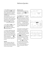
Multiroom Operation 32 The AVR85 is fully equipped to operate as the control center for a sophisticated multiroom operation with optional remote IR sensors, speakers and power amplifiers. Although some multiroom installations will require the services of a specially trained installer, it is possible for the average do-it-yourself hobbyist to install a simple remote room system. For additional information on using the AVR85 in multiroom installations we suggest that you contact your dealer or custom installer. Installation The key to remote room operation is to link the remote room to the AVR85's location with wire for an infrared receiver and speakers or an amplifier. IR Link The remote room IR receiver should be connected to the AVR85 via standard coaxial cable. Plug the IR connection cable into the Multi jack b on the AVR85's rear panel. If other Harman Kardon compatible source equipment is part of the main room installation, the Remote Cont. Out jack d on the rear panel should be connected to IR IN jack on the CD player or cassette deck. This will enable the remote room location to control source equipment functions as well as the remote room input and volume. NOTE: All remotely controlled components must be linked together in a daisy chain. Connect the IR OUT jack of one unit to the IR IN of the next to establish this chain. Audio Link Depending on the distance from the AVR85 to the remote room, two options are available. One option is to run high-quality, shielded audio interconnect cable from the AVR85's location to the remote room. At the remote room, connect the interconnect cable to a stereo power amplifier. The amplifier will be connected to the room's speakers. No volume control is required, as the AVR85 and the remote IR link will provide that function. At the AVR85, plug the audio interconnect cables into the Multi Out jacks i on the AVR85's rear panel. NOTE: The remote power amplifier must have signal sensing capability or be left on constantly to assure automatic operation at the remote room. As an alternative, place the amplifier that will provide power to the remote location speakers in the same room as the AVR85, and connect the Multi Out jacks i on the rear panel to the audio input of the remote room amplifier. Use the appropriate speaker wire to connect the optional power amplifier to the remote speakers. High-quality wire of at least AWG14 is recommended for long multiroom connections. IMPORTANT NOTE: Any cables run inside walls should be CL3/FT4 rated, or carry any other certification that is required by the NEC, NFPA or state and local building and electrical codes. To avoid interference, audio and speaker cables should not be parallel to, or in the same conduits with AC cables. If you have any questions about multiroom wiring consult your dealer, custom installer or a licensed contractor or electrician. Setup Once the equipment connections have been made, the AVR85 needs to be configured for multiroom operation by following these steps: 1. Press the Select button j to bring up the MAIN MENU. Press the ¤ button i four times or until the ⁄ or ¤ buttons i to position the on-screen cursor >is pointing next to SETUP MENU (See figure #1). Press Select. 2. The menus required for multiroom setup are on SETUP MENU 4, so it is necessary to reach that screen by using the ¤ button on each of the first three menus that appear until the cursor is on the next to the bottom line, GO TO SETUP MENU 2. Press Select and repeat this procedure until SETUP MENU 4 (see figure #17) is on the screen. 3. At this menu (see figure #17) you may select between fixed and variable control using the ‹ or › buttons i. Select VARIABLE if you wish to have a remote zone's volume be controlled through an optional remote link connection and to activate Source Link that changes the input feed to the remote room whenever the main room input source is changed. Select FIXED if you wish to have the remote zone input source and volume remain constant. When the desired choice is highlighted in reverse video press the ¤ button until the on-screen cursor is next to SET LEVEL.
-
 1
1 -
2
-
3
-
4
-
5
-
6
-
7
-
8
-
9
-
10
-
11
-
12
-
13
-
14
-
15
-
16
-
17
-
18
-
19
-
20
-
21
-
22
-
23
-
24
-
25
-
26
-
27
-
28
-
29
-
 30
30 -
 31
31 -
 32
32 -
 33
33 -
 34
34 -
 35
35 -
 36
36 -
 37
37 -
 38
38 -
 39
39 -
 40
40
 |
 |