Harman Kardon CITATION RECEIVER Owners Manual - Page 6
ANTENNA, rkinBAL
 |
View all Harman Kardon CITATION RECEIVER manuals
Add to My Manuals
Save this manual to your list of manuals |
Page 6 highlights
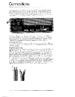
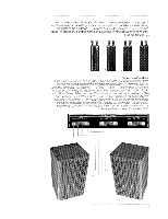
Repeat the procedure for the left speaker system, taking care to observe the coding of the conductors as described for the right speaker. Two additional pairs of speakers may be connectedin the same way to the SPEAKER 2 and SPEAKER 3 connectors. If the code has been followed as described, your speakers will have been connected "in phase:" Phasing is important for solid bass and precise lateral location of the sound source. The Operations section of this manual will describe a listening test that permits you to check for proper phasing after you have completed the other connections. Connecting AM Antennas Caution: Do not mistake the ferrite loopstick AM antenna for a handle. Its bracket cannot support the weight of the Citation Receiver. The Receiver should never be lifted, pulled, or pushed by means of the AM antenna. There is a ferrite loopstick AM antenna on the rear of the Citation Receiver. which can be swivelled to improve reception of distant stations. Moving the AM antenna aside will reveal terminals for external antennas. The terminal marked AM ANT provides connection for a "long wire" AM antenna. AM reception over extremely long distances can be obtained with a well-designed long wire antenna. High fidelity dealers, especially those who have experience with amateur and shortwave radio, can supply an appropriate long wire AM antenna. AM ANTENNA FM ANTENNA GNO rkinBAL 1 75f1 75 r' 30012 BAL 7512 e 30012 BAL 7511 ® ® 30012 BAL 7512 7512 ® ® ci 30052 LEAD-IN 7512 LEAD-IN 7512 LEAD-IN Connecting FM Antennas A T-shaped FM dipole antenna is supplied with the Citation Receiver. However. reception will be greatly improved if the Receiver is connected to an outdoor FM antenna system. Some apartment buildings provide a master television antenna system which can be used for FM. Some cable television systems and television antennas in private homes may also be used for FM reception. Two types of outdoor antenna leadlin cable -300 ohm and 75 ohm -are commonly used. Either one can be connected to the Citation Receiver. Ifyour antenna cable is 300 ohm., it willbe flat with a conductor at each edge. If the cable does not endin bare conductors orlugs, carefully cut away about 1-1/2 inches of the insulation material from the center of the cable, making sure not to damage either conductor. Strip offabout one quarter inch ofinsulation from each conductor and connect one conductor to each of the two terminals marked 30012 BAL on the rear of the Citation Receiver 4
-
 1
1 -
 2
2 -
 3
3 -
 4
4 -
 5
5 -
 6
6 -
 7
7 -
 8
8 -
 9
9 -
 10
10 -
 11
11 -
 12
12 -
13
-
14
-
15
-
16
 |
 |
