Harman Kardon CITATION RECEIVER Owners Manual - Page 8
receptacles.
 |
View all Harman Kardon CITATION RECEIVER manuals
Add to My Manuals
Save this manual to your list of manuals |
Page 8 highlights
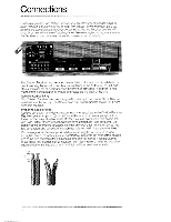
Connecting Tape Equipment The Citation Receiver provides facilities for both recording and playback with cassette, cartridge, and open-reel tape decks or recorders. MON TAPE 2 OUT MON OUT 0 0 LEFT • MON RIGHT OUT • t. • OUTPUT LI LaR INPUT OUTPUT L „a',„ 111 " I if #AfIfliffifi R INPUT • Using the signal cables provided with your tape deck, connect the left and right outputs of the tape deck to the TAPE 1 MON receptacles on the rear of the Receiver Connect the left and right inputs of the tape deck to the TAPE1 OUT receptacles of the Receiver. If you have a second tape deck, repeat the procedure using the TAPE 2 PITON and OUT receptacles. Push all plugs in as far as they will go so that they are seated snugly As a convenience, additional receptacles for TAPE 2 IN and OUT may be found on the right side of the front panel of the Citation Receiver. These are provided to allow the temporary connection of a second tape deck after the Receiver is installed. without having to turn the Receiver around. Note that these are quarter-inch "phone" receptacles, and not RCA receptacles as on the rear panel. (Each phone jack carries both left and right channels, so you will find only one receptacle for input, and one receptacle for output on the front panel.) The front panel TAPE 2 receptacles are wired in parallel with the rear panel TAPE 2 receptacles. Do not connect two tape decks simultaneously to the front and rear TAPE 2 receptacles. Interaction between the decks, even with one deck switched off, may reduce or distort the signal. Connecting Other Equipment Signal processing accessories may be connected to the TAPE MON/TAPE OUT or the PRE AMP OUT/MAIN AMP IN receptacles. Such accessories include audio equalizers. noise reduction processors, and dynamic range enhancers. To connect any accessory to the PRE AMP OUT/MAIN AMP IN receptacles, first remove the special patch plugs. This will interrupt the flow of signal in the Receiver. With no accessory equipment connected, the patch plugs must be left in place for the Receiver to operate. LEFT PREAMP OUT A'.. I MAIN. AMP IN . I '• • - LEFT RIGHT 'eii•rfir . NIGHT F&TER fti 6
-
 1
1 -
2
-
 3
3 -
 4
4 -
 5
5 -
 6
6 -
 7
7 -
 8
8 -
 9
9 -
 10
10 -
 11
11 -
 12
12 -
 13
13 -
14
-
15
-
16
 |
 |
