Harman Kardon CITATION RECEIVER Owners Manual - Page 7
Phono, Preamp
 |
View all Harman Kardon CITATION RECEIVER manuals
Add to My Manuals
Save this manual to your list of manuals |
Page 7 highlights
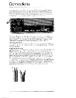
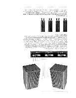
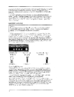
If your cable is 75 ohm, it will be round with either two protruding wires or a threaded coaxial connector. If the cable ends in bare wires connect the wire that forms the outer mesh braid to the terminal marked GND, 75g. Connect the solid, copper-colored wire protruding from the center of the cable to the terminalimmediately to the left of the first. Ifyour 75 ohm lead has a threadedcoaxial connector, tighten it onto the threadedantenna receptacle marked 750. Ifno outdoor antenna is available, connect the lugs of the dipole antenna (supplied with the Receiver) to the 300 c2 BAL terminals. The position of the antenna is impor- tant for optimum reception. The dipole willperform bestifits arms are carefully extended in a straight horizontal line and the entire antenna is fixed to the wall or tacked to the back of a shelf. Connecting Turntables The Citation Receiver provides two sets of inputs for turntables. Each turntable will have its own signal cables for the left and right channels. Consult the turntable owner's manual and determine which of the cables is the left channelsignal cable. Insert the pluginto the upper PHONO 1receptacle on the rearpanel of the Citation Receiver. Insert theplug of the right channelsignal cable into the lowerPHONO 1receptacle. Press both plugs in as far as they willgo so that they are seated snugly If the turntable has a separate ground wire, connect it to the knurledlug marked GND on the Receiver. To connect a second turntable, repeat the procedure using the PHONO 2 receptacles. 7 na-s, • PHONO 2 PREAMP ROrt GND AUX MON GND GND A SUBSONIC FILTER switch is located on the rear panel near the PHONO input receptacles. The filter protects the Receiver and speakers from inordinate subsonic resonances produced by some turntable-arm-cartridge combinations. The SUBSONIC FILTER affects only the phono inputs. You may prefer the margin of safety provided by having the SUBSONIC FILTER switch set to the IN position. After following the procedure described in the Operations section of this manual, some critical listeners may prefer to have the switch in the OUT position. 5
-
 1
1 -
 2
2 -
 3
3 -
 4
4 -
 5
5 -
 6
6 -
 7
7 -
 8
8 -
 9
9 -
 10
10 -
 11
11 -
 12
12 -
13
-
14
-
15
-
16
 |
 |
