HP 14-an000 Maintenance and Service Guide - Page 57
Lift the pieces of tape along the side of the system board
 |
View all HP 14-an000 manuals
Add to My Manuals
Save this manual to your list of manuals |
Page 57 highlights
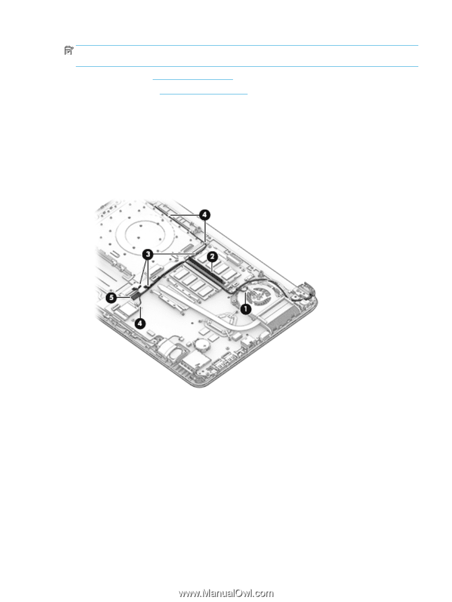
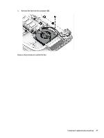
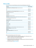
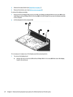
NOTE: When replacing the system board, be sure that the following components are removed from the defective system board and installed on the replacement system board: ● WLAN module (see WLAN module on page 36) ● Memory module (see Memory module on page 38) To remove the system board: 1. Remove the display cables by lifting the black and silver tape that secures the cable to the fan (1). 2. Lift the tape that covers the cable in the space between the two memory modules (2). 3. Lift the pieces of tape along the side of the system board (3). 4. Separate the antenna cable from the display cable (4). 5. Disconnect the display cable from the system board (5), and then remove the cables from their remaining routing paths. Component replacement procedures 49
-
 1
1 -
2
-
3
-
4
-
5
-
6
-
7
-
8
-
9
-
10
-
11
-
12
-
13
-
14
-
15
-
16
-
17
-
18
-
19
-
20
-
21
-
22
-
23
-
24
-
25
-
26
-
27
-
28
-
29
-
30
-
31
-
32
-
33
-
34
-
35
-
36
-
37
-
38
-
39
-
40
-
41
-
42
-
43
-
44
-
45
-
46
-
47
-
48
-
49
-
50
-
51
-
 52
52 -
 53
53 -
 54
54 -
 55
55 -
 56
56 -
 57
57 -
 58
58 -
 59
59 -
 60
60 -
 61
61 -
 62
62 -
63
-
64
-
65
-
66
-
67
-
68
-
69
-
70
-
71
-
72
-
73
-
74
-
75
-
76
-
77
-
78
-
79
-
80
-
81
-
82
-
83
-
84
-
85
-
86
-
87
-
88
-
89
-
90
-
91
-
92
-
93
-
94
-
95
-
96
-
97
-
98
-
99
-
100
-
101
-
102
 |
 |