HP 14-an000 Maintenance and Service Guide - Page 61
Display assembly, Disconnect the power from the computer
 |
View all HP 14-an000 manuals
Add to My Manuals
Save this manual to your list of manuals |
Page 61 highlights
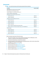
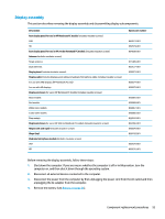
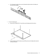
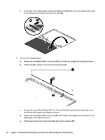
Display assembly This section describes removing the display assembly and disassembling display subcomponents. Description Raw display panel for use in HP Notebook PC models (includes insulator screws) FHD HD Raw display panel for use in HP 245 G5 Notebook PC models (includes insulator screws) Antenna (includes insulator screws) Single antenna Dual antennas Display bezel (includes insulator screws) Display cable (includes display panel cable and webcam/microphone cable; includes insulator screws) For use with FHD displays (HP Notebook PC only) For use with HD displays Display enclosure for use in HP Notebook PC models (includes insulator screws) Black models Red models White silver models Turbo silver models Blue models Display enclosure for use in HP 245 G5 Notebook PC models (includes insulator screws) Hinges (left and right) (includes insulator screws) Hinge (top) Webcam/microphone module (includes insulator screws) VGA HD Spare part number 860573-001 860574-001 864838-001 813485-001 859127-001 858073-001 858074-001 858075-001 858065-001 858068-001 858067-001 858066-001 858070-001 860456-001 858076-001 858702-001 860575-001 860576-001 Before removing the display assembly, follow these steps: 1. Shut down the computer. If you are unsure whether the computer is off or in Hibernation, turn the computer on, and then shut it down through the operating system. 2. Disconnect all external devices connected to the computer. 3. Disconnect the power from the computer by first unplugging the power cord from the AC outlet and then unplugging the AC adapter from the computer. 4. Remove the battery (see Battery on page 26). Component replacement procedures 53
-
 1
1 -
2
-
3
-
4
-
5
-
6
-
7
-
8
-
9
-
10
-
11
-
12
-
13
-
14
-
15
-
16
-
17
-
18
-
19
-
20
-
21
-
22
-
23
-
24
-
25
-
26
-
27
-
28
-
29
-
30
-
31
-
32
-
33
-
34
-
35
-
36
-
37
-
38
-
39
-
40
-
41
-
42
-
43
-
44
-
45
-
46
-
47
-
48
-
49
-
50
-
51
-
52
-
53
-
54
-
55
-
 56
56 -
 57
57 -
 58
58 -
 59
59 -
 60
60 -
 61
61 -
 62
62 -
 63
63 -
 64
64 -
 65
65 -
 66
66 -
67
-
68
-
69
-
70
-
71
-
72
-
73
-
74
-
75
-
76
-
77
-
78
-
79
-
80
-
81
-
82
-
83
-
84
-
85
-
86
-
87
-
88
-
89
-
90
-
91
-
92
-
93
-
94
-
95
-
96
-
97
-
98
-
99
-
100
-
101
-
102
 |
 |