HP 14-an000 Maintenance and Service Guide - Page 65
To remove the display panel
 |
View all HP 14-an000 manuals
Add to My Manuals
Save this manual to your list of manuals |
Page 65 highlights
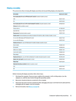
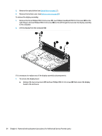
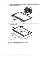
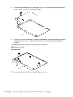
c. Lift to disengage the adhesive that secures the webcam/microphone module to the display, and then remove the module (2). 3. To remove the display panel: a. Remove the four Phillips PM2.0×2.4 screws that secure the display panel to the enclosure. b. Rotate the display panel off the display enclosure (1) to gain access to the display cable connection on the back of the panel. Component replacement procedures 57
-
 1
1 -
2
-
3
-
4
-
5
-
6
-
7
-
8
-
9
-
10
-
11
-
12
-
13
-
14
-
15
-
16
-
17
-
18
-
19
-
20
-
21
-
22
-
23
-
24
-
25
-
26
-
27
-
28
-
29
-
30
-
31
-
32
-
33
-
34
-
35
-
36
-
37
-
38
-
39
-
40
-
41
-
42
-
43
-
44
-
45
-
46
-
47
-
48
-
49
-
50
-
51
-
52
-
53
-
54
-
55
-
56
-
57
-
58
-
59
-
 60
60 -
 61
61 -
 62
62 -
 63
63 -
 64
64 -
 65
65 -
 66
66 -
 67
67 -
 68
68 -
 69
69 -
 70
70 -
71
-
72
-
73
-
74
-
75
-
76
-
77
-
78
-
79
-
80
-
81
-
82
-
83
-
84
-
85
-
86
-
87
-
88
-
89
-
90
-
91
-
92
-
93
-
94
-
95
-
96
-
97
-
98
-
99
-
100
-
101
-
102
 |
 |
c.
Lift to disengage the adhesive that secures the webcam/microphone module to the display, and
then remove the module
(2)
.
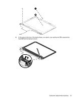
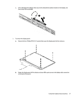
3.
To remove the display panel:
a.
Remove the four Phillips PM2.0×2.4 screws that secure the display panel to the enclosure.
b.
Rotate the display panel
off
the display enclosure
(1)
to gain access to the display cable connection
on the back of the panel.
Component replacement procedures
57