HP 2000-150CA Service Guide - Page 75
Optical drive connector cable, Remove the two Phillips PM2.0×5.0 screws
 |
View all HP 2000-150CA manuals
Add to My Manuals
Save this manual to your list of manuals |
Page 75 highlights
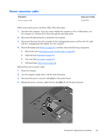
Optical drive connector cable NOTE: The optical drive connector cable is included in the Cable Kit, spare part number 646119-001. Before removing the optical drive connector cable, follow these steps: 1. Shut down the computer. If you are unsure whether the computer is off or in Hibernation, turn the computer on, and then shut it down through the operating system. 2. Disconnect all external devices connected to the computer. 3. Disconnect the power from the computer by first unplugging the power cord from the AC outlet and then unplugging the AC adapter from the computer. 4. Remove the battery (see Battery on page 43), and then remove the following components: ● Optical drive (see Optical drive (select models only) on page 44) ● Keyboard (see Keyboard on page 53) ● Top cover (see Top cover on page 56) Remove the optical drive connector cable: 1. Release the optical drive cable from the clips (1) built into the base enclosure. 2. Remove the two Phillips PM2.0×5.0 screws (2) that secure the optical drive connector to the base enclosure. 3. Remove the optical drive connector (3) from the base enclosure. Reverse this procedure to install the optical drive connector cable. Component replacement procedures 67
-
 1
1 -
2
-
3
-
4
-
5
-
6
-
7
-
8
-
9
-
10
-
11
-
12
-
13
-
14
-
15
-
16
-
17
-
18
-
19
-
20
-
21
-
22
-
23
-
24
-
25
-
26
-
27
-
28
-
29
-
30
-
31
-
32
-
33
-
34
-
35
-
36
-
37
-
38
-
39
-
40
-
41
-
42
-
43
-
44
-
45
-
46
-
47
-
48
-
49
-
50
-
51
-
52
-
53
-
54
-
55
-
56
-
57
-
58
-
59
-
60
-
61
-
62
-
63
-
64
-
65
-
66
-
67
-
68
-
69
-
 70
70 -
 71
71 -
 72
72 -
 73
73 -
 74
74 -
 75
75 -
 76
76 -
 77
77 -
 78
78 -
 79
79 -
 80
80 -
81
-
82
-
83
-
84
-
85
-
86
-
87
-
88
-
89
-
90
-
91
-
92
-
93
-
94
-
95
-
96
-
97
-
98
-
99
-
100
-
101
-
102
-
103
-
104
-
105
-
106
-
107
-
108
-
109
-
110
-
111
-
112
-
113
-
114
-
115
-
116
-
117
-
118
-
119
-
120
-
121
-
122
 |
 |
