HP 2000-150CA Service Guide - Page 76
Display assembly, Disconnect the display panel cable
 |
View all HP 2000-150CA manuals
Add to My Manuals
Save this manual to your list of manuals |
Page 76 highlights
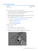
Display assembly Description Spare part number 15.6-in, HD, LED display assembly (includes microphone and wireless antenna transceivers and cables) AntiGlare display assembly with pewter finish equipped with a webcam 646842-001 AntiGlare display assembly with pewter finish not equipped with a webcam 646841-001 BrightView display assembly with pewter finish equipped with a webcam 646844-001 BrightView display assembly with pewter finish not equipped with a webcam 646843-001 Before removing the display assembly, follow these steps: 1. Shut down the computer. If you are unsure whether the computer is off or in Hibernation, turn the computer on, and then shut it down through the operating system. 2. Disconnect all external devices connected to the computer. 3. Disconnect the power from the computer by first unplugging the power cord from the AC outlet and then unplugging the AC adapter from the computer. 4. Remove the battery (see Battery on page 43), and then remove the following components: ● Optical drive (see Optical drive (select models only) on page 44) ● WLAN module (see WLAN module on page 47) ● Keyboard (see Keyboard on page 53) ● Top cover (see Top cover on page 56) ● USB board (see USB board on page 62) ● Power connector cable (see Power connector cable on page 63) Remove the display assembly: 1. Disconnect the display panel cable (1) from the system board. 2. Release the wireless antenna cables from the clips (2) built into the base enclosure. CAUTION: Support the display assembly when removing the following screws. Failure to support the display assembly can result in damage to the display assembly and other computer components. 3. Remove the four Phillips PM2.5×6.0 screws (3) that secure the display assembly to the computer. 68 Chapter 4 Removal and replacement procedures
-
 1
1 -
2
-
3
-
4
-
5
-
6
-
7
-
8
-
9
-
10
-
11
-
12
-
13
-
14
-
15
-
16
-
17
-
18
-
19
-
20
-
21
-
22
-
23
-
24
-
25
-
26
-
27
-
28
-
29
-
30
-
31
-
32
-
33
-
34
-
35
-
36
-
37
-
38
-
39
-
40
-
41
-
42
-
43
-
44
-
45
-
46
-
47
-
48
-
49
-
50
-
51
-
52
-
53
-
54
-
55
-
56
-
57
-
58
-
59
-
60
-
61
-
62
-
63
-
64
-
65
-
66
-
67
-
68
-
69
-
70
-
 71
71 -
 72
72 -
 73
73 -
 74
74 -
 75
75 -
 76
76 -
 77
77 -
 78
78 -
 79
79 -
 80
80 -
 81
81 -
82
-
83
-
84
-
85
-
86
-
87
-
88
-
89
-
90
-
91
-
92
-
93
-
94
-
95
-
96
-
97
-
98
-
99
-
100
-
101
-
102
-
103
-
104
-
105
-
106
-
107
-
108
-
109
-
110
-
111
-
112
-
113
-
114
-
115
-
116
-
117
-
118
-
119
-
120
-
121
-
122
 |
 |
