HP Chromebook x360 13.3 inch 13b-ca0000 Maintenance and Service Guide - Page 40
I/O board, Remove the I/O board
 |
View all HP Chromebook x360 13.3 inch 13b-ca0000 manuals
Add to My Manuals
Save this manual to your list of manuals |
Page 40 highlights
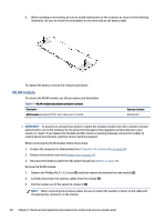
4. Remove the speakers from the computer (4). To install the speaker, reverse this procedure. I/O board To remove the I/O board, use these procedures and illustrations. Table 5-8 I/O board description and part number Description I/O board I/O board cable Spare part number N24428-001 N24422-001 Before removing the I/O board, follow these steps: 1. Prepare the computer for disassembly (see Preparation for disassembly on page 25). 2. Remove the bottom cover (see Bottom cover on page 27). 3. Disconnect the battery cable from the system board (see Battery on page 28). Remove the I/O board: 1. Disconnect the two cables from the ZIF connectors on the board (1). 2. Remove the three Phillips M2.0 × 3.5 screws (2) that secure the bracket, and then remove the bracket (3). 3. Remove the Phillips M2.0 × 3.0 screw (4) that secures the board. 4. Remove the board from the computer (5). I/O board 35
-
 1
1 -
2
-
3
-
4
-
5
-
6
-
7
-
8
-
9
-
10
-
11
-
12
-
13
-
14
-
15
-
16
-
17
-
18
-
19
-
20
-
21
-
22
-
23
-
24
-
25
-
26
-
27
-
28
-
29
-
30
-
31
-
32
-
33
-
34
-
 35
35 -
 36
36 -
 37
37 -
 38
38 -
 39
39 -
 40
40 -
 41
41 -
 42
42 -
 43
43 -
 44
44 -
 45
45 -
46
-
47
-
48
-
49
-
50
-
51
-
52
-
53
-
54
-
55
-
56
-
57
-
58
-
59
-
60
-
61
-
62
 |
 |
